The BRYMSTON RR #28

THE BRYMSTON RR #28 – TURNOUTS = part 3

After a hiatus caused by customers and a long birthday weekend away driving trains progress has been made with the stub turnouts. The next job was to make the moving rails and their operating arms/wires.  The plan is to operate them from underneath the baseboard.

To that end I wanted dropper wires from the underside of the rail to locate with a mechanism under the board. Criteria were: –

  • Silver soldered so it won’t come undone
  • Consistent placement so that the rails become a known standard to mate with the mechanism below the board.

That said I need a jig to me.

That opened a bit of a can of worms that included a mild rebuild of my bandsaw whilst equipping it with a metal cutting blade to cut the aluminium for the jig.

On the jig the aluminium block is screwed to the back plate. In this picture there are two bits of rail glued to the far face leaving a channel for the rail to be soldered locating it parallel to the back plate but spaced off it.

At the far right is an end stop, This has a Vee filed in it so not only does it set the distance it prevents the rail deflecting up or down.

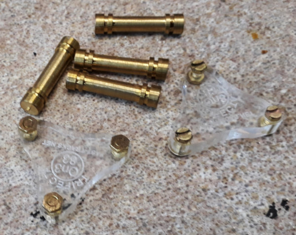
The dropper wire holder consists of two bits of brass tube silver soldered to a bit of brass angle. Two bits of tube were used because I had them to hand but they resulted in a happy accident. One bit moved a smidgen such that there is a very slight misalignment. The happy result is the dropper wire is held tightly and stays where its put. A couple of layers of card spaced the dropper holder up to the centre line of the rail.

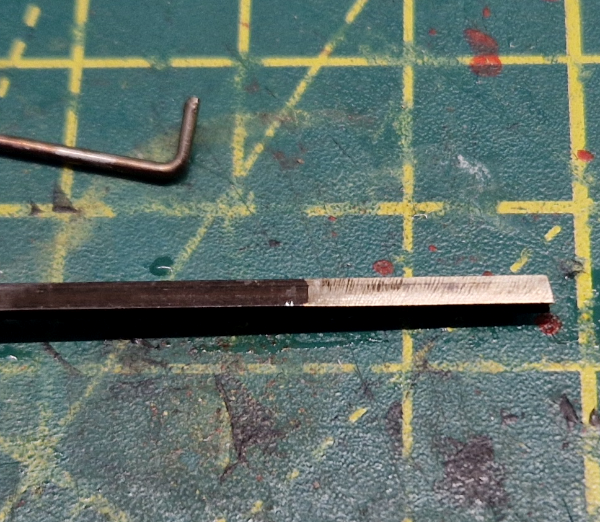
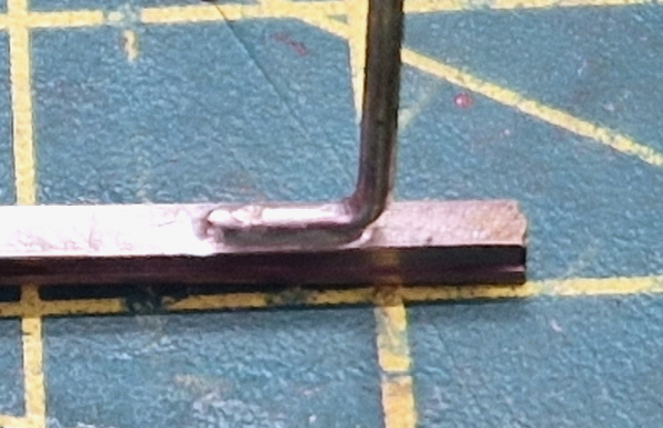
The droppers are 1mm diameter nickel silver wire. They are bent in a pair of pliers with the width of the blade acting as the depth gauge for the length of the bent bit.

Once bent they are held in a pin vice and were touched on a powered sanding disk to create a small flat on the bottom to increase the surface contact of the soldered joint.

The rail being used is Micro Engineering code 83 and its the weathered variety so the bottom face has to be cleaned of the weathering compound. Once clean both the rails and the droppers were left to soak in pickling acid for awhile –  precise time being one cup of tea and two biscuits. This gives them a final clean prior to soldering.
What is silver soldering? Its a harder and higher temperature method of joining two metals. Whereas your soft soldering with an iron uses a temperatures in the 150 to 350’C range this is in the 600-900’c range. Its advantages for modelers is that it can be the first part of an assembly and subsequent soft soldering won’t make it come undone. In this case its that its a stronger bond and unlikely to fail in a location where fixing it would be a right pain in the nether regions.
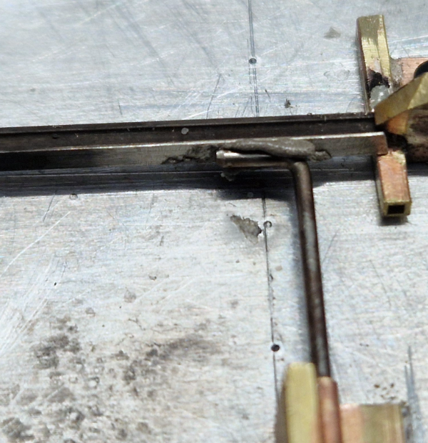
With the parts cleaned  they’re place in the jig and aligned.

A smear of EasyFlow silver solder paste was spread on the rail before the wire was pushed into place and then a bit more was added with the blade of a scalpel. The solder paste is a combination of silver solder and paste flux. Mine is in a syringe and you can squirt it directly on to the work but as it takes some squeezing out I prefer to do so on to a surface and then pick it up and place it with a bit of wire or a blade.

At this point you could heat this to red hot with a small blowtorch and the solder would flow but following from an earlier experience doing the crossing vees I decided, after I did the first with fire, to see if my resistance soldering rig would do it.

Resistance soldering is done by passing a current through a joint that has either solder paste in it or the parts have been tinned. (coated with a layer of solder). It is more usually used for soft soldering where you place the parts in a ground plane (tin foil) connected to the unit with a crocodile clipped lead. The parts are assembled and held in the right place with a carbon probe connected to the live side of the unit. When all is in the right place a foot pedal is pressed and current flows through the joint melting the solder. Once its flowed the pedal is released to stop the current whilst the probe hold it all together until the joint cools and solidifies,

To do the higher temperature silver soldering I use two carbon probes so the current passes directly through the join. An early mod was to add a bit of business card as an insulator when I couldn’t figure why the transformer was buzzing until i realised the bodies of the two probes were touching the aluminium backing plate.

The video shows the actual soldering as it happens and you see the solder flash into the joint as soon as the correct temperature is reached.  I filmed this with my phone which was so close that I was placing the probes by watching them on the screen. Those who do keyhole stuff via cameras have just gone up in my estimation!
After allowing it to cool the soldered the joined thing gets taken off the jig and given another soak in pickling solution as this removes all the flux and soldering debris.

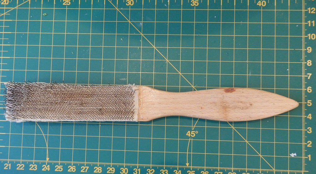
It just needs a light buff with an abrasive brush to clean it up ready for use.


I did wonder about some mods to the jig such as replacing the toolmakers clamp that holds the rail in place with a cam lock affair but instead I got on and just made enough closure rails to do all the turnouts on the layout and a few spares.

The next instalment will hopefully be about installing these and cosmetically finishing these turnouts


Coming soon

Loading

THE BRYMSTON RR #27

THE BRYMSTON RR #27 – TURNOUTS – part 2

In the last episode we got as far as hiving made template in a photo package – I use Affinity. Now to prepare a base to build them on.

Firstly they were laid out on a sheet of 2mm ply to mark it and cut it to size. A thin, 0.4mm I think, layer of ply was added where the ties for the non moving parts of each turnout was added. This is done because the moving parts run on etched baseplates making them higher than on plain ties so the rest has to be lifted by that amount.

I then got a base of 10mm ply that would remain rigid whilst the turnouts were built. This was covered with a layer of 5mm foamboard so that any drillings that went though the turnout base went into something soft. The turnout bases were then fastened to the build board using a trick I saw in a guitar building You Tube channel. Both the underside of the turnout base and  the top of the foam board were covered in blue painters tape. One then had blobs of thick cyanoacrylate glue applied whilst the other was sprayed with accelerator. They’re then pressed together to hold them. The theory is that when you want them apart the tape just peels.  We’ll see as I’ve stuck spikes through it!

York Model Railway Exhibition was fast approaching and this was to be my show demo build so emphasis turned to making parts in prep that would be difficult at the show.

First up were crossing vees as I wanted these to be silver soldered to make them both rigid and impervious to later soft soldering activity.

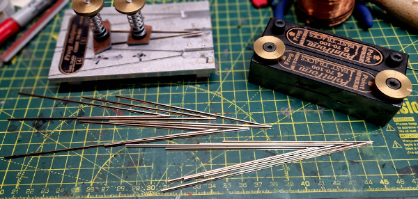
The jig is a Fast Tracks “Frog Helper” to which I have added the clamps. I think that the intent is that for soft soldering fingers hold it safely enough but as I was planning on pointing a blow torch at it and getting the rail red hot I thought clamps would be better than fingers.

I needed three #5’s and one #4 but I made several spares of each. They were filed using the Fats Tracks Pointform tool.

These come with Allen Screws as seen on the back one but I have done a mod to add thumbwheels as I can never find the Allen Key.

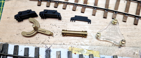
Next bright idea was these printed jigs hold all the bits for a point frog in the right place upside down whilst some wires were soldered across to hold it all together. There’s two, one for #5’s and one for #4’s

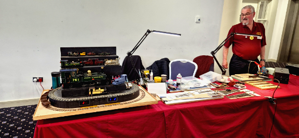
At the show three of us had a table on the top floor with a display of different scale narrow gauge modes and we were variously building track, wagons and coaches.

The show is a three day affair and is very convivial both at the show and at the after hours relaxing which may have been in a pub.

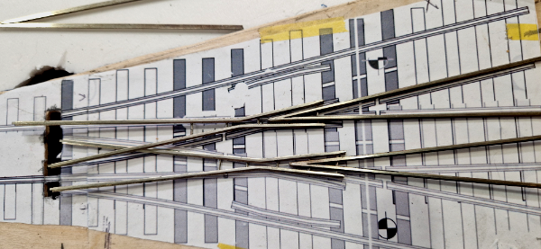
Turnout work commenced by making up the frogs and then laying them out over the plans. Ties were then added on to the plan adjusted to miss any of the wires holding the frog together.

There is now a bit of a gap in photo coverage as on day two at the show I had forgotten my phone (aka camera) whilst on day three I forgot.

The rough summery is that the frogs were laid on the plan and cut to make the combined or leading crossing. There is probably science that could be applied but it was mostly guessing and estimating. Once happy that vee was soft soldered and the entire unit glued down to the ties using track gauges. With that done other rails were added using the track gauges.

Show now over and back at home I was keen to crack on now with all the tools to hand and with my camera handy.

This is part of my collection of track gauges some bought and some 3D printed. The best “standard” is the Perspex one, this gets used where gauge is critical. The roller gauge is a bit naff as its too small in diameter and the grooves aren’t deep enough. Some of the printed ones also feature fixtures to hold check rails in place.

Eventually that got all the fixed rails in place. At this point they are only glued down. That said having wanted to move a rail I can say they are stuck in place and aren’t going anywhere.

They are glued with aliphatic glue applied by a pipette nozzle fitted to the bottle. This wicks in under the rail and as it starts to go off surplus can be removed with a wet paintbrush.

The rails are now fully spiked as well as glued.

They actually aren’t “spiked” as such as they are pushed into drilled holes and then glued by brushing the aliphatic glue on, leaving it for a couple of minutes whilst it wicks around the spike and down the hole then wiping/wicking any surplus off with a wet paintbrush.

Surplus glue leaves a shiny mark on the ties but a whizz over with a nylon brush in a rotary tool removes it. Final job for this chapter was to cut the rails for insulation gaps between each of the sections

The next instalment will cover making the moving parts, jigs to attach the operating wires and some cosmetics. I’m still thinking about the jigs design

 coming soon

Loading

THE BRYMSTON RR #26

THE BRYMSTON RR #26 – TURNOUTS

Firstly, its been ages since I added anything to The Brymston RR Saga. This is a true reflection of how much I have done in the last 18 months. I may have messed up and made a reckless commitment!  Immediately after this years Trent Valley Group Modelling Day in January some idiot [me] may have promised the organiser [also me] that The Brymston RR could appear at the January 2027 event.  First thoughts were that if me and me told no one then we might get away with not mentioning it again but the real screw up was that I did it in front of witnesses.

Now at the moment only the curved board has any track on it, and then only on the lower level. Its also the only board with the start of any scenery on it!

Better get on and lay some track then. Hold your horses. A reminder, this layout is 0n3 and there is virtually no ready to run track available so its all going to need to be hand built.

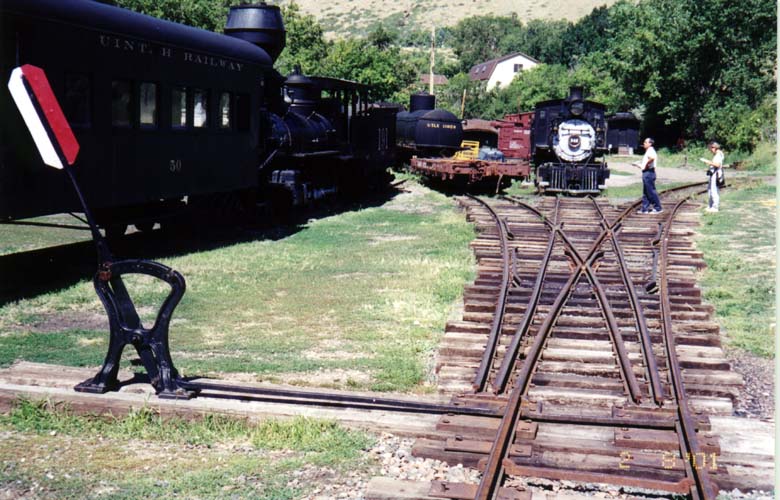
An added variation is that all the turnouts on the layout are going to be stub turnouts.

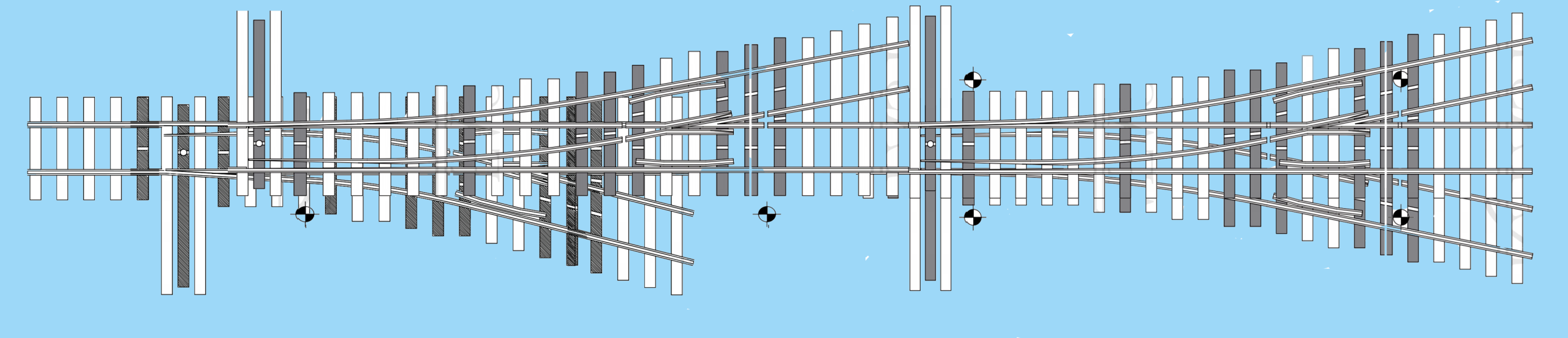
If you are not familiar with these then have a look at the picture of the three way stub. There are no blades. The approach rails are just moved to line up with the route you want to take. The advantage of them is that they cab be shorter than a standard turnout. Disadvantages are they are low speed, no positive locking of the rails and you’re actually bridging a gab crossing from the switch rails to the fixed rails. They were popular for their simplicity and whilst the main line moved away from them they remained common on industrial, and low budget railroads such as a logging and minerals concern like The Brymston RR.

THE TRACK PLAN

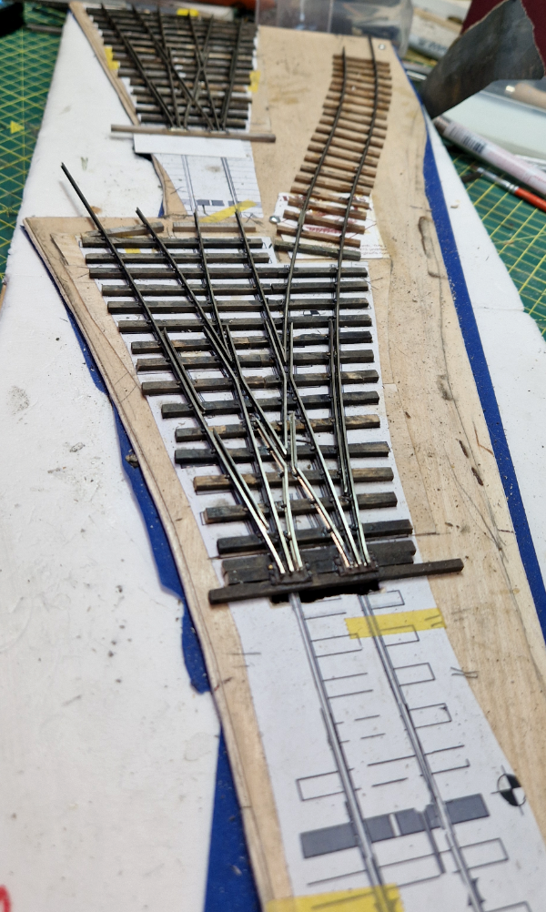
Might as well start with the difficult stuff! Entry on this board is straight into an assymetric three way stub. The line up to the higher level is a #5 angle whilst the one towards the front of the layout is a #4. This leads straight into a second three way but this is a symetric #5. The #4 route will limit what can go that way but that line will likely be the storage track with something like the cabeese parked on it. By taking the straight road through each you get to 2 road of the shed and it being a straight run through the turnouts anything that makes it round the curve will be able to make it to the shed,

THE CUNNING PLAN

As I type this the 2026 York Model Railway Show is two weeks away and I have a demo table there with two mates so I have decided its three days of point building for me. There are some things that need doing in advance for this and one is to make templates

The first problem is that Fast Tracks free printable turnout templates don’t include three ways or stubs so some editing was attempted

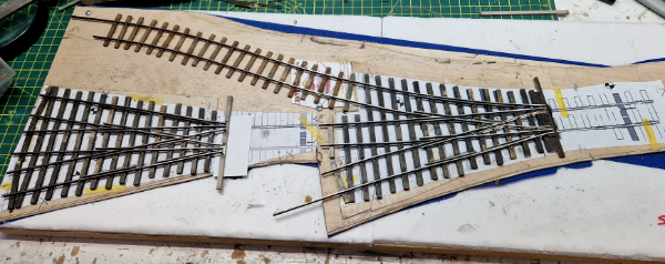
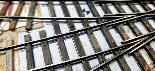
When it looked like that would work some more effort was put into modifying the standard points with this result

After that the templates were laid on the layout to check they fit so a removable base could be made for them. That’s ongoing and I’ll report that in the next episode.

Loading

The Brymston RR #25- Vandalism?

CONSIDERING AN ACT OF VANDALISM!

Earlier we were discussing the loco shed for the Brymston RR and I made a mock up of something in card. It’s gone not further than that until just now….

I was sat in the stores packing customers orders and having a moment of idly staring in to space waiting for the printer to get its act together when I spied a box on the top shelf. Intrigued I got it down.

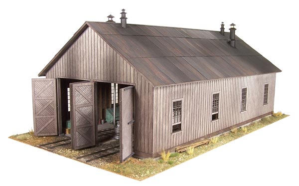
It was a kit for a loco shed. Not quite what I want but it could work with mods

OUEOMain.jpg

The act of vandalism?

It’s a Raggs to Riches kit for Ouray Engine House.  Raggs kits are the mutts nuts both in terms of buildability and accuracy and they’re no longer available Raggs having retired.

Modifying this kit would probably be the model equivalent of putting a UPVC conservatory on a grade 1 listed building.

Loading

Brymston RR– #24–Bendy Engine Progress

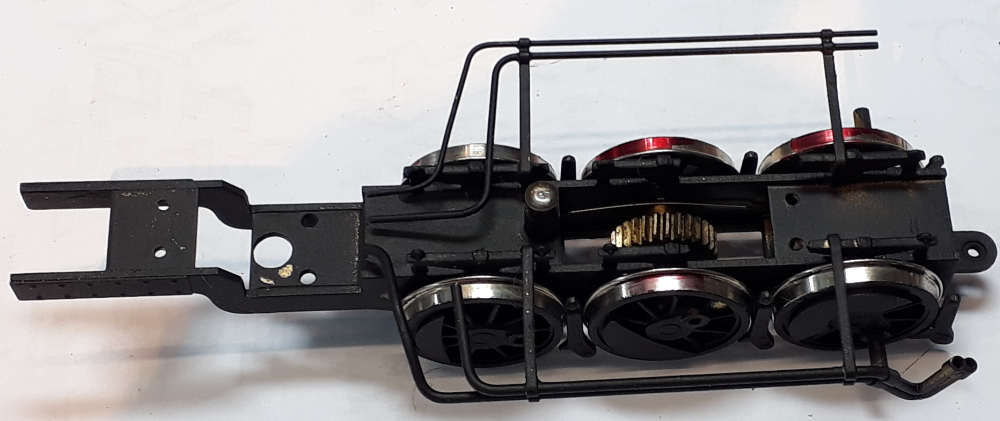
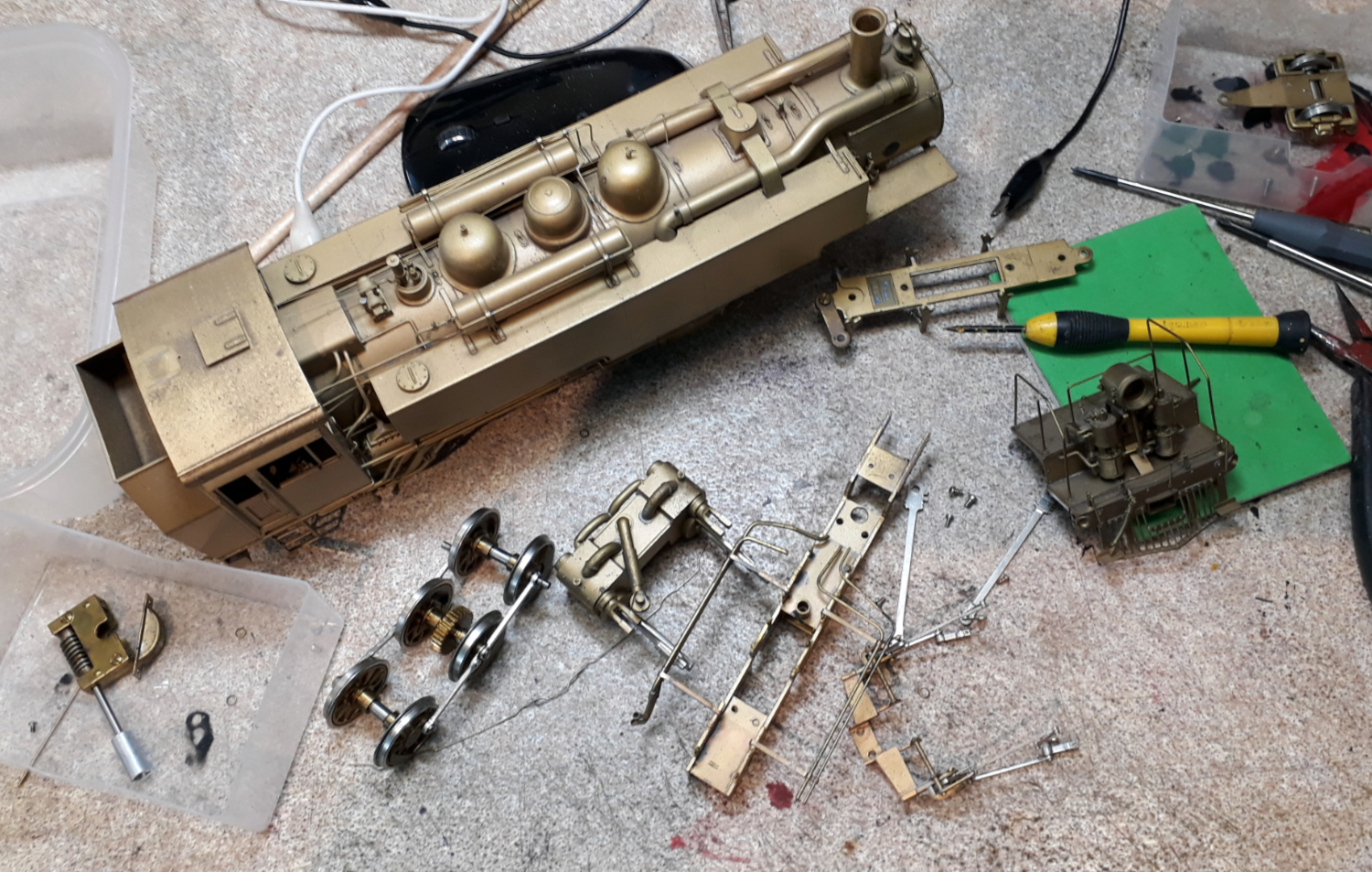
In odd moments I have been progressing the sorting out of one of the bendy engines. In the first episode about this bendy engine I dismantled the front truck and reduced it to it component parts. “Off Camera” as it were, the parts have been cleaned and sprayed with an etching primer ready for reassembly.

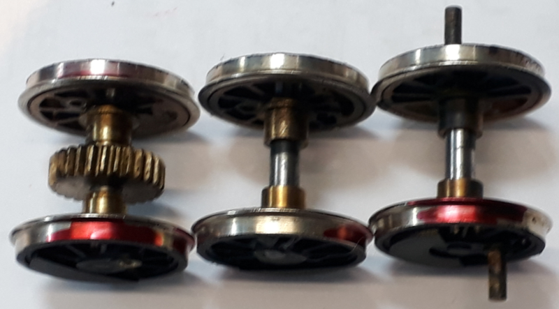
First move was to establish some polarities to be sure I put the wheels in the right way round. Tradition on American brass models is to have wheelsets insulated on one side only so the other side conducts to the frame. Then, on a tender engine, the tender is live to one rail and the loco to the other. You can see the problem here – no tender.

On this loco, being a Mallet there is a fixed power unit and an articulated one. The fixed unit has one side live to the frame and wiper pickups to the insulated side and then on the articulated truck just one side live to the rail. So its got 3 wheel pickup to one rail and six wheel pickup to the other rail. I intend to add wipers to the articulated end but for now I just need to make sure the wheels live to the frame on both are on the same side.

This was done with a multi-meter on its continuity (beep) setting. PANIC. It beeped to both sides! For now I went with the wipers as a clue and resolved to sort the potential issue out when it was the rear bits turn for overhaul.

Using the beep test the live wheel was identified with red marker pen and then assembled into the frame. I WISH IT HAD BEEN THAT EASY!  The driving wheels are sprung and, unusually for American brass they actually work. Usually you’ll see a coil spring above each axle box that is so strong it does nothing other than press the wheel hard against the keep. This has wire longitudinal springs that hook behind two pins on each side and then bear against the axle bearings. Neat when together but I used up a lot of fitters language getting them in.

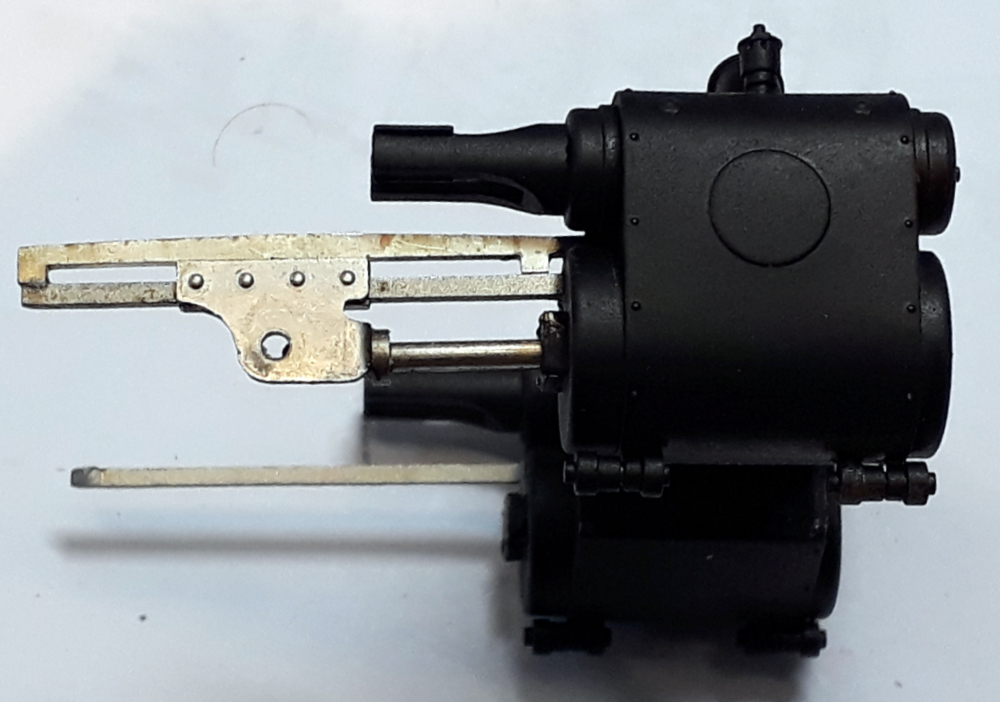
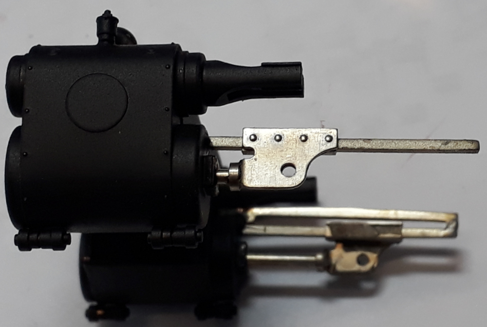
Next to add would have been the cylinders but here I found a problem. This first picture is how they should look with the guide bar above the slidebar and with the rear end keeping the crosshead captive.

The clue that something was amiss was the crosshead falling out of the other side. Looks like tomorrow mornings task involves whittling some nickel silver fret offcuts to shape.

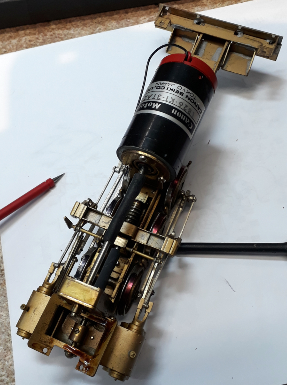
Finally for this small work session I decided to have a look at the fixed power unit and disconnected the motor. A retest of the wheel insulation revealed there to be no problem. The beep to both sides was because the fancy Canon motor is such low resistance that there was a path through the motor from the insulated wheels.  Some power to the motor wires had it all running. It has a small squeak once per revolution and its seems tight. There’s some dubious looking oil oozing out of the spur gear box but that will all get cleaned out when this bit get overhauled

Coming soon


Loading

Brymston RR #23 Moving Mountains

I do like it when a plan comes together.

This is what all the mess in the dirty stuff workshop has been about. The two boards that are currently the Brymston Railroad are joined together and the mountain back scene is all mounted and in place and, at least from this angle, you can’t see the join.

The join is a bit more obvious when looking from this angle but I have a plan – maybe. It all looks a lot better just from the reduction in the amount of bright white primer there is on show.

The backscenes are adhesive backed vinyl and, were I doing it again, I’m not sure I’d get the adhesive backed ones again. The instant tack and a desire to stick to anything and everything barring where you want it too made getting them smooth difficult but then it wouldn’t stick at the edges.

I think a PVA giving more adjustment time would be better. I’ve had to glue the edges with a vinyl glue and tape them with low tack tape and once that’s hard I plan several layers of acrylic varnish to build up a hard edge.

Shortly the long board will go back upstairs to the model room whilst the corner board will get more foam added to build up the mountains, the tunnel mouth added and the track ballasted keeping the messy stuff downstairs. I do need to get myself a freehand hot knife foam cutter.

The cunning plan for the join is a half relief tree with its first branches high enough to let a train past and with its top somewhere in the clouds but that will be a late addition as I don’t fancy tree making.

As the layout develops the scenery and buildings will slowly hide the mountain backscene so its glimpsed through the structures, trains and trees and will merge, well, into the background.

The corner board and the fiddle board need a bit of engineering to mate them as they weren’t intended for each other. The fiddle board may just be temporary as its been repurposed from another stalled project.


Loading

BRYMSTON RR-#22-SNOOKERED!

Can you see an abrasive blaster in this image?

I’ve snookered myself with two ongoing projects. In the image you can see the backscene project waiting for filler to harden in a room that could do with being a bit warmer. It’s all still a bit too soft to risk moving any of it. More on boards soon.

Onward then with the bendy engine project.

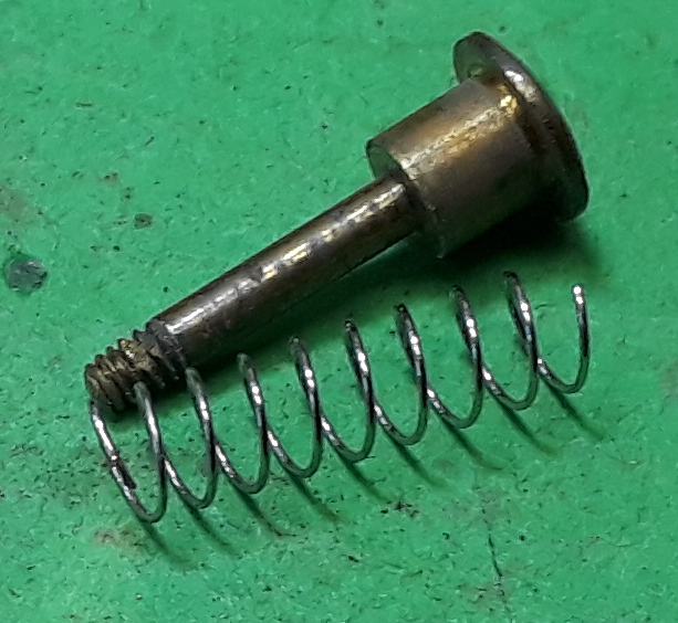
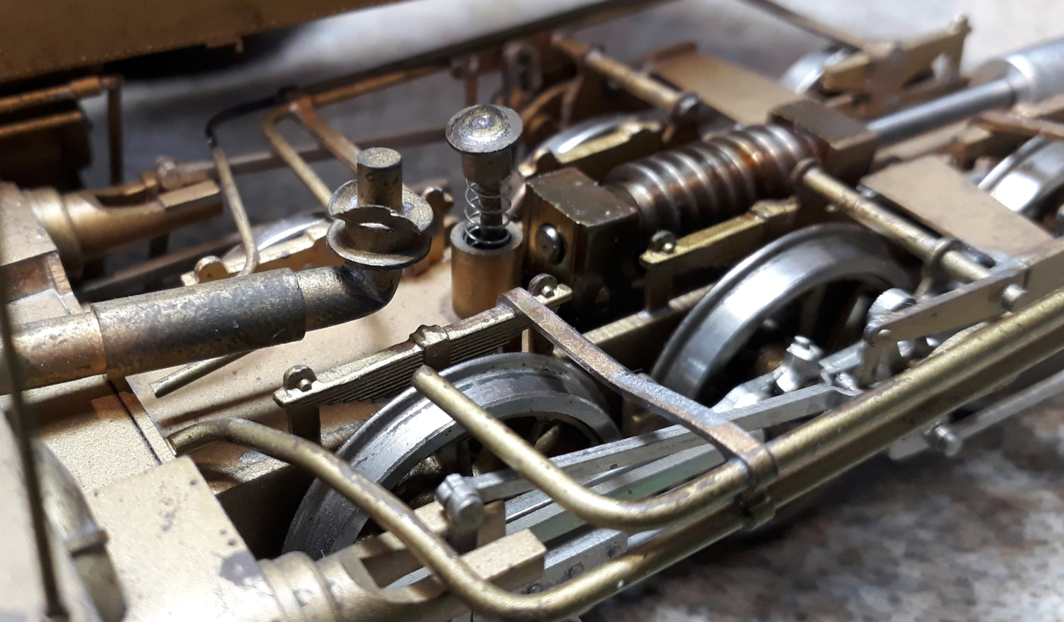
So, we had displaced springy things and disconnected U/J’s but the root of the problem is this piece of pipe detail.

One end screws to the power bogie allowing it to swivel side to side with a small amount of up and down permitted. The other end slides in a slot in the underside of the smokebox so it can slide along the slot as the bogie swivels.

The pipe is inserted in the slot at one end as its shaped like a keyhole. Its supposed to limit the amount the bogie can drop if picked up by the body.

It didn’t which is why the sprung bearing got out and the UJ undid.

The problem can be seen in the pipe image above. The smokebox slides between the two washers so it the right hand (top) one that has to support the weight and its too twee and has bent.


When in place it should look like this.


The plan to fix it?

First job is to flatten the bent washer and of that I’ve turned a bit of brass with a hole up the middle to make a small anvil/press tool. I’m hoping a few light taps will flatten the bent washer.

A new turned washer that it s bit thicker will then be soldered to the back of the bent washer to reinforce it.

The abrasive blast cabinet?  These models often had some impenetrable lacquer applied and there is other paint and contamination on the part so my plan was to give it a rough time in the blaster so I am at least trying to solder to clean brass. Its whereabouts? Behind all the boards I can’t move for awhile.

Coming Soon

Loading

BRYMSTON RR – #21 – BENDY ENGINE BOTHER

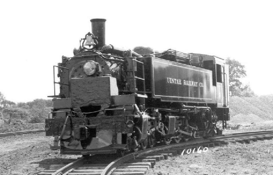
OK, in earlier episodes you’ve seen my Bendy Engine Uintah 2-6-6-2 Mallet checking the curves. I have two of these aiming to model both the Uintah engines.

One, the shiniest, did service on my sales display for many years ticking over on a rolling road. It went back in the display case due to a slipping drive shaft. In the medium term (its already past that) it’ll stay on display.

It’s the other one that’s been used for gauging trials and as I’ve just picked it up off the layout prior to moving the board to do what was to be the next instalment of the board saga the front power unit fell away and disconnected its drive shaft.


I also noticed that the sprung plunger that is supposed to transfer some weight from the body to the truck was trying to escape.

I thought popping that back in would be a five minute job. Boy have I opened a can of worms!


It should fit in here like this but a bit further in and retained by a nut underneath.


Removing the front power unit was easy by just undoing one screw. It went downhill from there. I thought “just pop the keeper plate off and put the retaining nut back on the plunger.


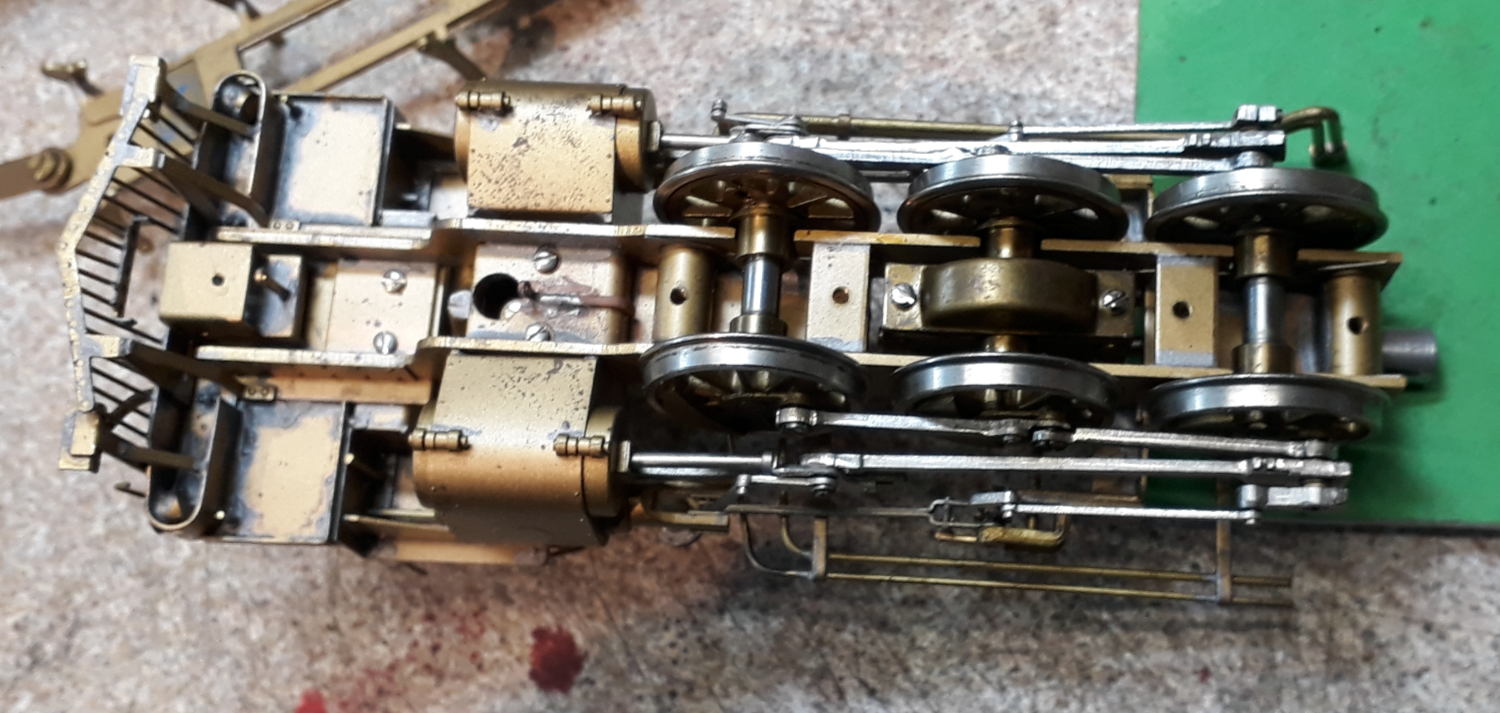
Nope! The bit we need access to is behind the stretcher and between the gearbox and the front axle.

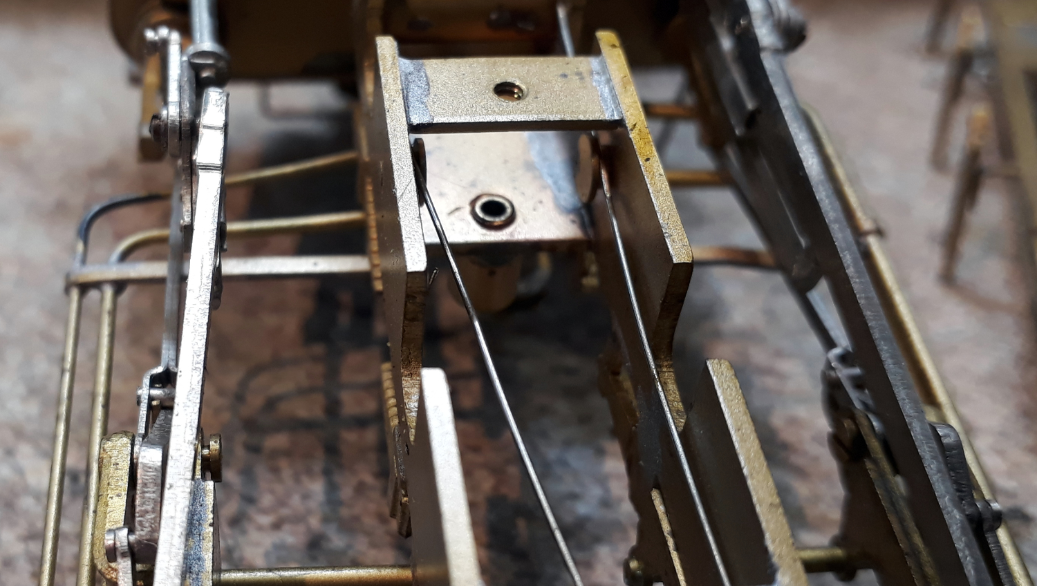
The image to the right jumps ahead a bit but the plunger stem should pop through the lower hole and have a nut on it.


So, I thought, I’ll just undo the gearbox as it could probably do with a re-lube and drop the wheels out. It went downhill from there!

Having got so far with this dismantling now might be the time to start some of its paint job and upgrade whilst I am this far in so I went a bit mad and took the front truck as much to bits as possible.

An upgrade it needs doing are to add pickups to one side of its drivers and, if I can, to the front truck. You could argue this isn’t necessary as both sides of the rigid truck pickup and then bendy truck picks up through one side of the frames. Fitting keep a keep alive with its DCC sound install would avoid any stalling but I have two reasons for doing so.

  1. In my opinion even with a keep alive you can’t have too many pickups and,
  2. My layout uses DCC with position detection by sensing motor current and it’s a confined layout so this loco needs to trip the detection as it arrives at a point not after half the loco has passed the point.

The front headlight also needs converting from an ornament in to a working headlight which will mean drilling some holes and running some wires across the truck.

Almost inevitably I’ll follow this up with doing the fixed truck so it matches and I can address one of its Achilles heals. Most of the drive has universal joint but in the depths of the fixed truck there is one that is a bit of silicon tube and they’re prone to slipping on the shaft.

This episode was written whilst the trucks parts were drying following a swim in mu ultrasonic cleaner.

Coming Soon


Loading

BRYMSTON RR – #20 – MAKING A SCENE

Episode 20 in this flurry of writing should get the story up to the point the layout is at now but it won’t be the end for long as I have

  • Committed to taking all or some of the layout to Mickleover Members day in January
  • Found my Mojo for doing the layout and aim to keep going with it.

I am fortunate to have two work spaces. I have what would be the garage (if it had a garage door) downstairs and you might call this the heavy engineering workshop as it has my lathe, mill, drills, 3D printer, injection moulder and all manner of other tools. It’s the messy workshop.

Upstairs I have my model room which management reliably informs me should be the master bedroom. I had visions of a large layout but EDM Models has most of the space in a room fitted out with kitchen units to make cupboard space and worktop. As explained earlier the realisation that the big layout wasn’t going to happen led to the modules idea and episode 10 had a diagram of where it sits in the room.

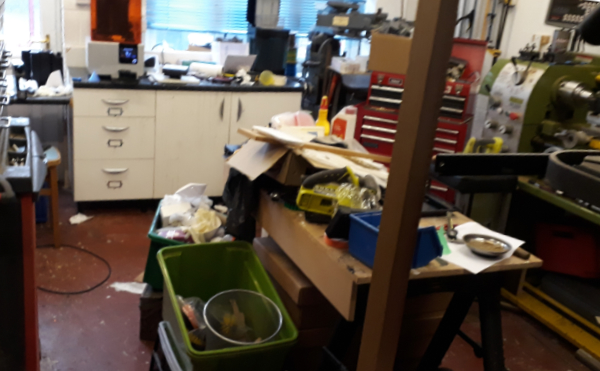
Both locations have a problem. In the messy workshop there is access off the kitchen and its way too easy to do the “where shall I put this” – “stuff it in the workshop”. It’s not helped by me not being very tidy natured and the 3D printer operating on the basis of actual prints being a by product of it making a mess!

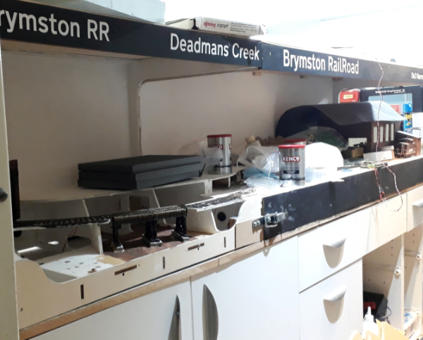
Upstairs the layout offers a way to convenient shelf and nine months of inactivity had filled the shelf up. To be fair a lot of the clutter is actually layout making stuff but I have often joked about making the top cover a sloping top so I cant put stuff on it!

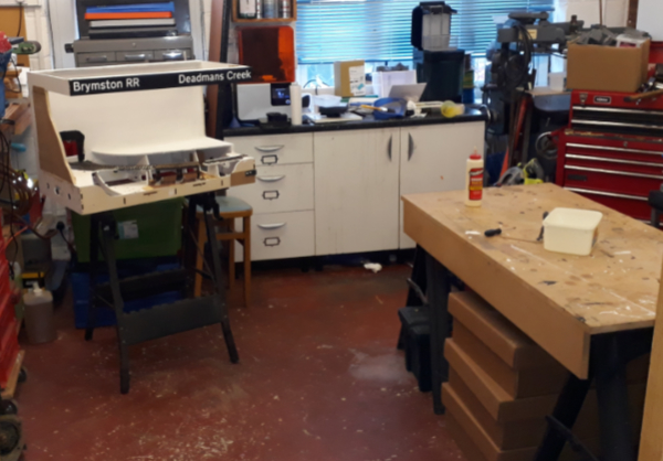
So, my modelling day started with a massive tidy up in both locations and took a good bit of the morning. The workshop now looks a lot better (with the help of selective photography). It is a constant surprise what you find. Anyone short of a leg

The reason for this tidy up in two locations is that this burst of modelling is going to be messy so the corner board of the layout needed to be in the downstairs workshop near the power tools.

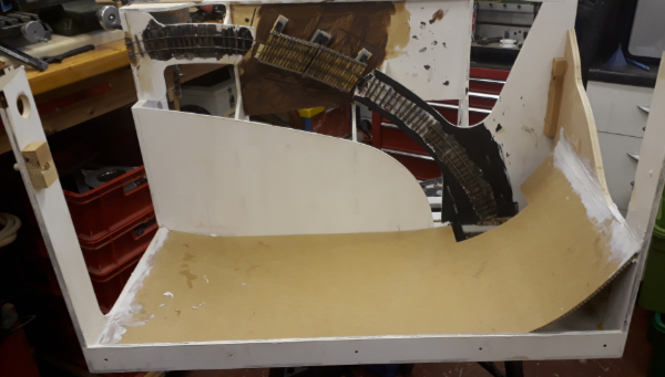
The aim of the game is to remove this sharp corner by fitting a curved backscene.

This is to be a sheet of flexi MDF and the bit of forward planning I alluded to was that I had purchased a sheet in advance. The idea is to avoid a sharp corner which is very difficult to scenic convincingly.

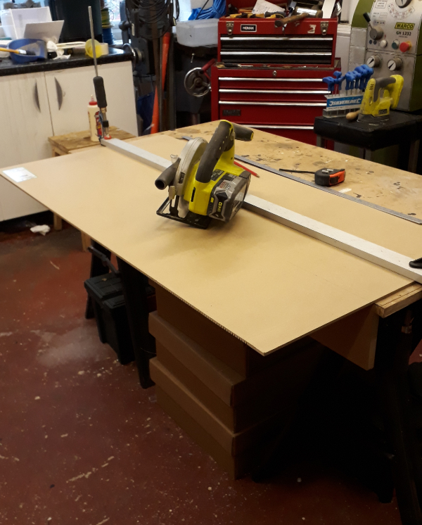
The first job, cutting it down to size, justified the move to the messy workshop as despite PPE, extraction on the saw the main product seemed to be dust!

The MDF was held down and my long cutting guide fitted to guide the circular saw. Despite lots of measuring and checking I always worry that I have got the guide offset wrong before cutting.

A coffee break was declared to let the dust settle.

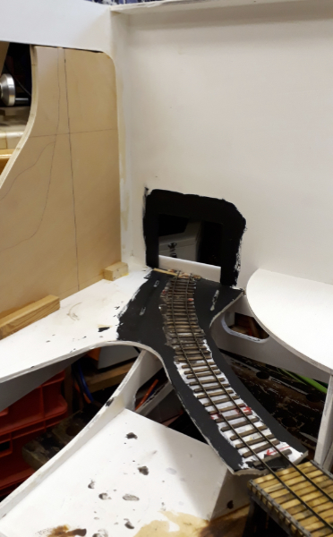
Having got the height right the MDF was placed on the layout to get the length right and to cut the hole for the tunnel.

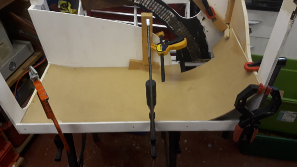
At this point there was an outbreak of bad language as the MDF instead of curving smoothly kinked as one of the grooves that make it flex split. This was repaired with a glued patch and something else was done for a while whilst it stuck. I also painted round the tunnel hole with wood working glue to seal the edges a bit.

Feeling my age interlude:

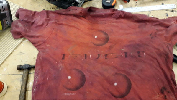
Whilst cleaning up I noticed the rag was an ancient T shirt

A Rush ‘ Hold Your Fire ‘ tour T shirt.

It doesn’t seem that long ago but it was April 1998 at the NEC I went to see them!

A wise man (I think it was Norm from the New Yankee Workshop) once said “There’s no such thing as too many clamps”. I agree and have deployed a fraction on mine here to hold the MDF backscene here whilst the glue dries.

If I remember rightly this was then end of day one and the glue was left to dry overnight and another baseboard project was got on with (more on that in another post soon).

Next morning it was filler time to feather the edges. Plan A didn’t work, Who’d have thought that the two part epoxy filler that’s been in the cupboard for at least ten years would have gone off.

Luckily I had some flexible decorating filler to hand that hadn’t gone off. Its downside being that it took a lot longer to harden.

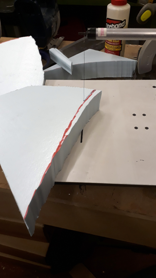
To pass the time I broke out the foam cutter. I use this about once every five years and every five years it reminds me of how crap it is but as I only use it so rarely I got justify getting a decent one.

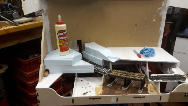
As I am aiming to keep the boards as light as possible the hills are to formed of dense foam blocks profiled to shape and glued together with PVA glue. This is another reason for being in the messy stuff workshop as this stuff goes everywhere.

The hills are starting to take shape. Next I need to find my hand held cutter (its had five years to hide) to shape them and to add the tunnel mouth mock up to position that in the contours. Once the rough contours are sorted it’ll all be covered in a hard shell coating (more mess).

That’s where we leave this episode. I have decided I like the back scene sheet idea and the other board will be getting a trip to the workshop for a similar treatment although it doesn’t have any of the tight corners on it.

[post views]

Loading

BRYMSTON RR #19 – A BRIDGE FOR THE GAP

As hinted at the end of the last update there is a change of subject for this one with developments on the corner board with a start made to create the hand laid track.

As is often my way I’ve made it complicated for myself but as the curve will be on the limit of minimum radius for some of the locos to go round it it I decided that I needed to ensure it was a constant curve with no kinks or tight bits in it.

It was also to be rail just glued into place initially with spikes added later so it was also important that the rail wasn’t trying to spring to straight.

I had two tools to help me sort this. One bought and the other designed and built by me.

The first gadget is a rail bender which allowed me to pre-bend the rail to the right radius so it laid in place without trying to straighten. This was a commercial unit I bought years ago from the people that do the fast track jigs.

The second tool was a frame I designed and 3D printed to hold the rail at the correct radius for the inner rail of the curve and ensured it was a constant sweep through the curve. With it the rail was positioned over the ties glued down to the baseboard, weighted down and glued. It was left overnight to dry fully.

The second rail was added with the first still held in the printed frame. To do this I used two sorts of track gauges.

The first were roller gauges and the other were a pair of 3 point gauges. The way I did it was to hold the second rail along its length with the rollers but next to where is was soldering it – oops forgot to mention that amongst the wood ties were some PCB ones – I used the three points as this puts a little bit of gauge widening in to the outer rail. Not much but every little helps.


In the orgy of foam board mocking up the layout I also produced a tunnel mouth so you can begin to see what it should look like.

The next job was to cut a gap in the plywood where the bridge is to go.


The resultant gap needs a bridge


First thought were of some sort of plate girder bridge as modelled here in foam board and with my Climax posing for scale.

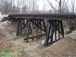
There was quite a lot of debate about bridges on one of the forums and in the end having been sent images like these I settled on a trestle


I sketched up some ideas in CAD. not detailed but enough to give me an idea


I had hoped to modify an Evergreen Hill Trestle kit I had but in the end it just became a source for the wood. That would was all a bit too regular so it got some abuse from a knife, wire brush and fire

With the rails unsupported and vulnerable across the gap I was keen to get a bridge in place asap. The bridge was built temporarily on a bit of plywood and was initially designed to pin together with cocktail sticks.

On its bit of ply it could then be placed under the rails and the deck timbers placed in the correct alignment. At this point I was debating whether to do timbers under the rail but in the end decided against it.

Clearly the bridge was still too low but it needed some foundations for the piers. These were cast in DAS stone compound with a very crude jig and on cling film so as to able to get it out.

These foundations were cast a smidge too thick anticipating some shrinkage and left to dry.  Once dried the bridge was packed up to touch the rails and the foundations sanded until they slipped into place with some packers. With them in place they were glued to the bridge and layout and the rails glued to the deck. A bit of weathering tidied it up and the track will get more when the adjacent sections have been ballasted.

With the bridge in place and with the rail supported and protected by it towards the end of March progress pretty much fizzled out until the weekend just gone when work resumed on a different aspect which provides the ideal point at which to end this episode.

[post views]


Loading