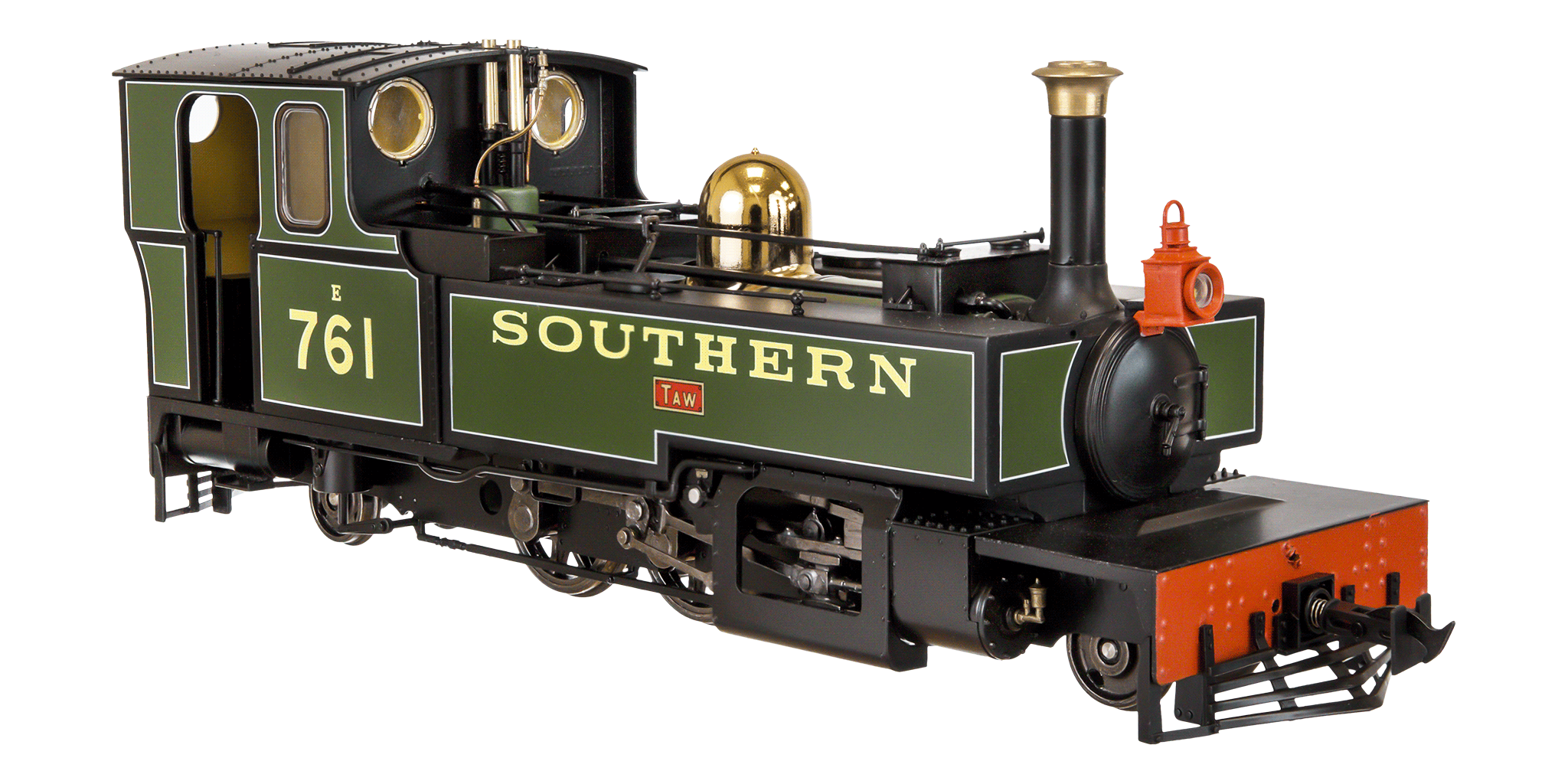
 There was a lot of enthusiasm for the subject when Lionheart Models announced their L&B models. After a long wait the models have arrived and they are superb.
In a small corner of the modelling world their was additional excitement when they saw this statement.
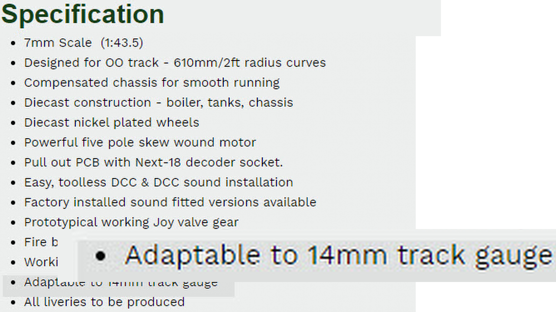 For the first time a manufacturer was offering RTR O14 stock or at least stock designed to be convertible easily.
The models were announced in September 21 and delivered in December 23 and throughout many were asking how the O14 compatibility was to be delivered and no answer was forthcoming.
I was fortunate enough to be able to speak to the designer throughout. Firstly, it became clear they either hadn’t really thought about it or hadn’t fully understood the implications. The result has been a steady stepping away from any commitment to 014. Firstly, replacement wheels for the loco’s got binned as too expensive against and unknown demand. (missed a trick in the ordering by not including any way to measure who wanted O14). Next it was a promise to do O14 coach wheels that got binned. Finally, when it was pointed out that the supplied wheel profile couldn’t even be simply re-gauged any pretence of compatibility became denial they ever offered it.
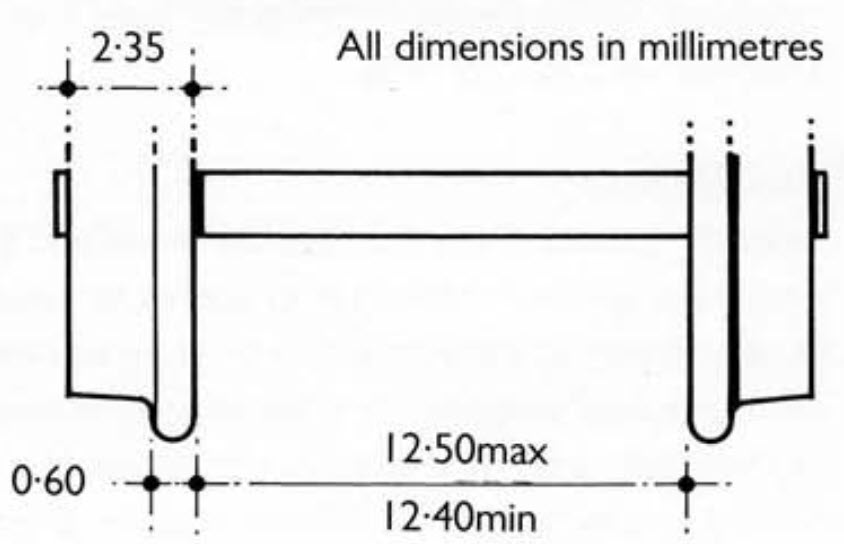 The models are supplied with a wheel profile that is understandably aimed at OO as that is the track that the majority will run on. The trouble for O14 is that the profile has a thick flange and a very generous root radius.
If you set the back to back dimension to 12.5mm as per the spec then the gauge is 14.3mm and the wheels sit in the track with no sideplay as they are actually sat on the radius. Wheelset would be hitting every crossing nose. Set the gauge correctly and the back to back is too narrow and wheels will be hitting all the check rails.
 Can it be Done?
I made the foolish offer* to do a regauging service before we knew the profile wouldn’t work.
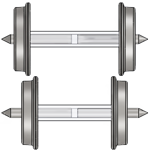
The coach wheels are two half axle assemblies pressed into a plastic muff. This is to make them split axle to collect power for the carriage lights. Each axle half is a turned brass wheel and half pin point axle. Initially it wasn’t apparent that the half wheel/axle were two pieces.
-* seems foolish at the moment as I am surrounded by dismantled wheels
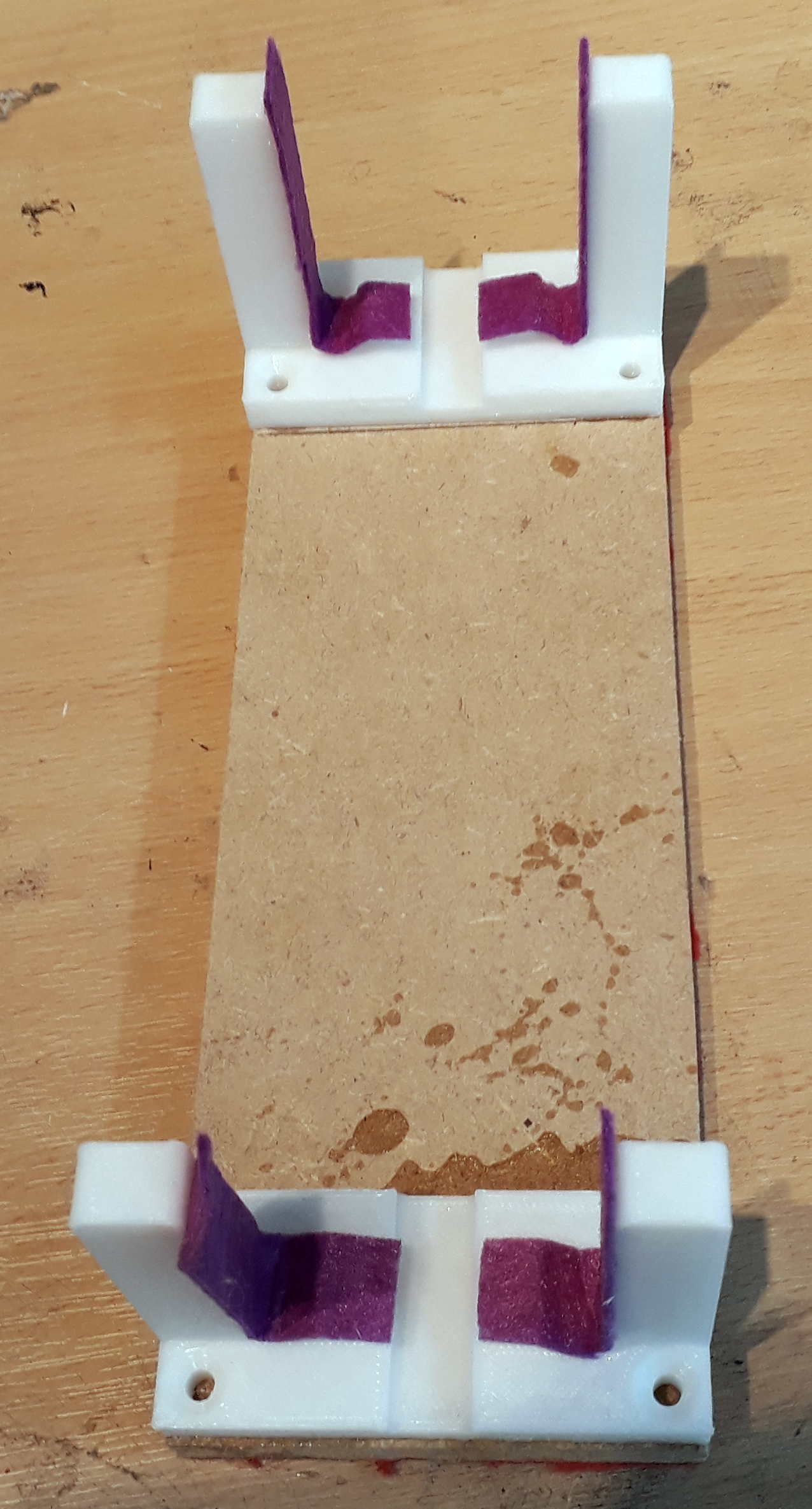 I have something around 60 coaches to re-gauge for customers so it was clear that a process was needed. Doing one or two yourself balancing them on your workbench with all the fine detail at risk is fine when its your coach you risk damaging. Something much better was going to be needed for customers expecting their models to be intact but with O14 wheelsets in them.
The first thing I did was use my new FDM printer to create cradles to hold a carriage upside down. The printed bits are glued to an MDF base and are lined with some felt. They are designed to hold the coach gently upside down with the weight taken on plain bits of the roof. The detailed centreline of the coach sits clear of anything that might damage it.
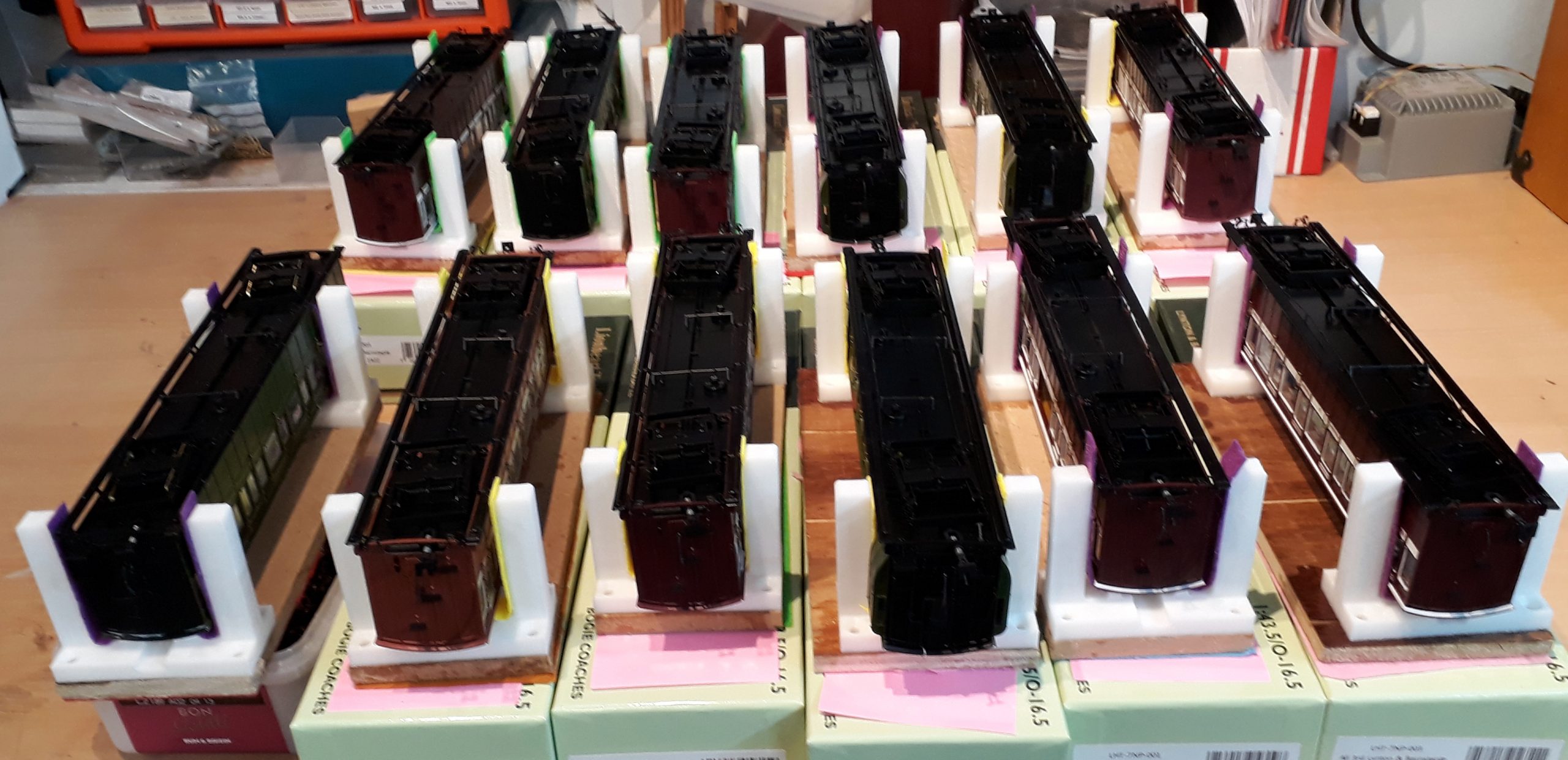 I printed twelve sets of cradles. The new FDM printer is a super high speed machine so it only took it two hours to print them all once I got the design how I wanted it and they provided a useful learning job for getting to grips with it.
The first batch of twelve coaches were then placed in the cradles whilst on top of their stock box that was labelled with the customers name. The potential for getting them mixed up is high!
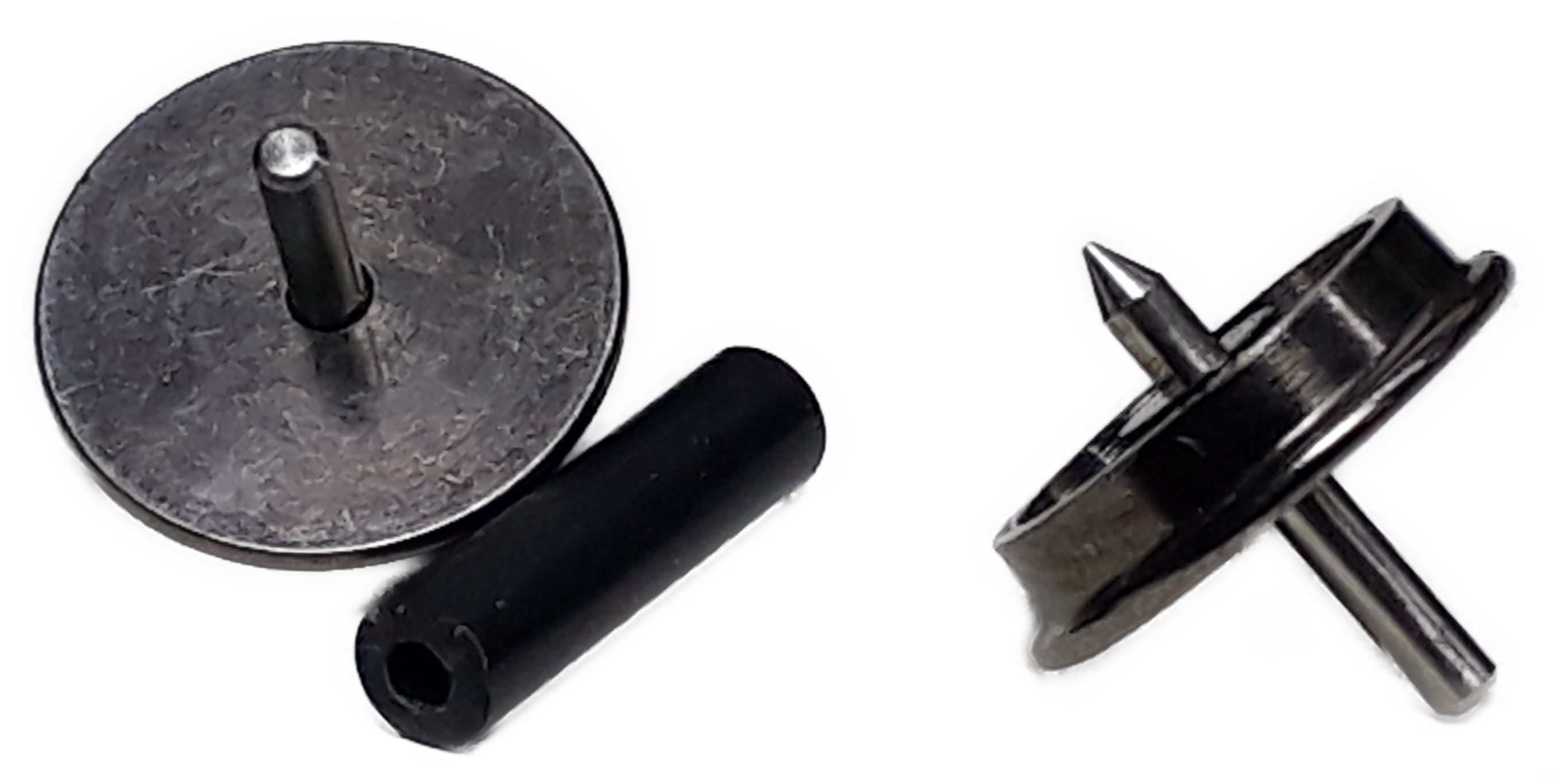 All the wheels were removed and the coaches moved to a safe place. An extra 10(ish) coaches worth of wheels were added to the pot from customers who had their coaches and just sent the wheels.
The wheels were then dismantled. Easy doing one, they pull & twist apart. Doing close on a hundred and its not long before the fingers had had enough. It took several goes giving the fingers a rest in between to get them all stripped.
Several set-ups with two lathes and two mini pedestal drills were engineered to make it a production line.
 Firstly, on lathe was set up with a 1.5mm collet to hold the wheel by the axle and a Scale7 profile tool set up, aligned and locked in the carriage. the spacer between the wheel and the collect moves the wheel out a fixed distance so that tool has clearance behind the flange. This lathe has a DRO so you can keep a check on cutting depths.
I’m going to say “accurate, repeatable & consistent” now as that is the whole purpose of these set ups. Doing around 250 wheelset in total is a different kettle of fish to doing your four coaches on your own bench in your own time. The profile tool reduces the flange and takes out some of the root radius so that it now complies with the standard.
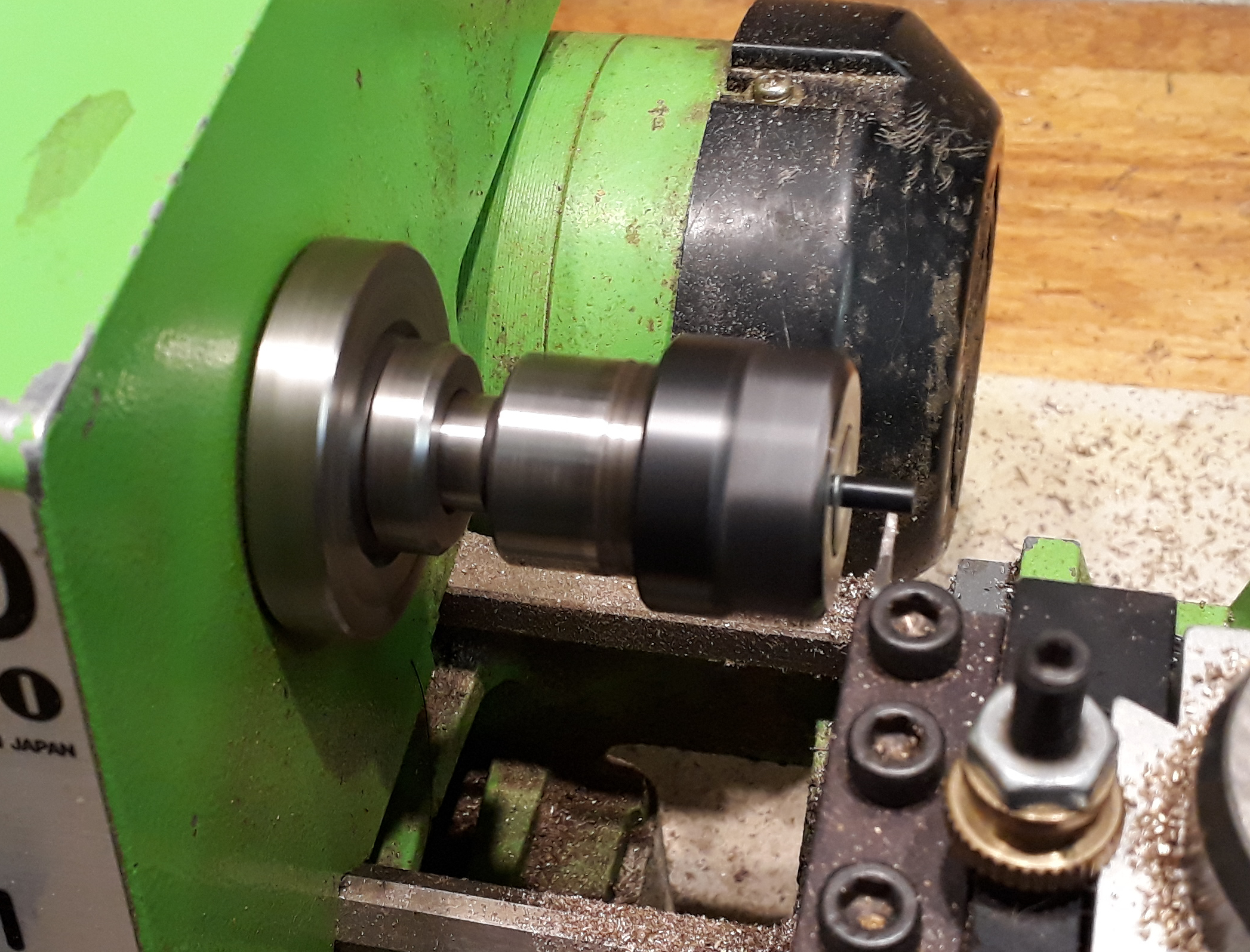 Next machine set up was my little lathe. It is fitted with a collet chuck that has a depth stop. This means the axle muffs can be inserted against the stop so as to be in a known position.
A parting blade in a locked carriage then shortens the muff by a known amount. Lastly a centre drill in the tailstock clears the swarf off the end and adds a little taper to guide the axle in when its all pressed back together. “accurate, repeatable & consistent” again.
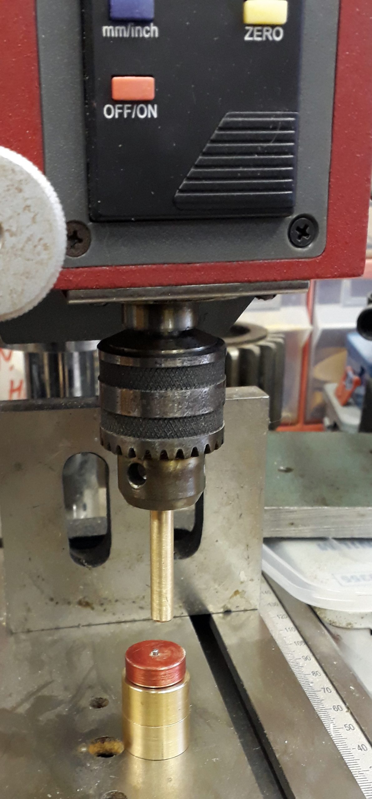 Next set up was one of the mini pillar drills as a press with three turned parts to control the action.
The lowest piece of brass is bored to hold the wheel by the tread and flange with a clearance whole for the stub axle.
There is then a piece in the chuck as the anvil. Its turned with a step in it so that its not relying on the chucks grip for the pressing forces as the chuck is pressing against a shoulder.
The red coloured bit of brass (coloured red to reduce the chances of me losing it) is the clever bit. For 14mm gauge the wheel needs to move along the axle by a specific amount so that whilst the back to back is 12.5mm the axle is still 24mm over the pin points which by design then means there is a insulating gap in the middle. The red spacer is the same thickness as the stub axle needs to still have to the back of the wheel so you press the axle until the anvil gets to the spacer. More “accurate, repeatable & consistent”
 The final set up uses my other mini pillar drill as a press to put the wheelsets back together again.
The top and bottom anvils aren’t quite a simple as they look. The are made up of two concentric tubes soldered to each other in such a way that the inner one with a 1mm bore bears on the end of the axle, but not on the pin point, whilst the other presses on the wheel centre at the same time. Having gone to all this trouble to get the wheel in the right place on the axle we don’t want to risk changing that as the wheelset it pressed back together.
This job might transfer to the mini lathe once all the muffs are shortened just to ensure that the two anvils are on a common centreline. These pictures were taken during the proving runs before the main production run.
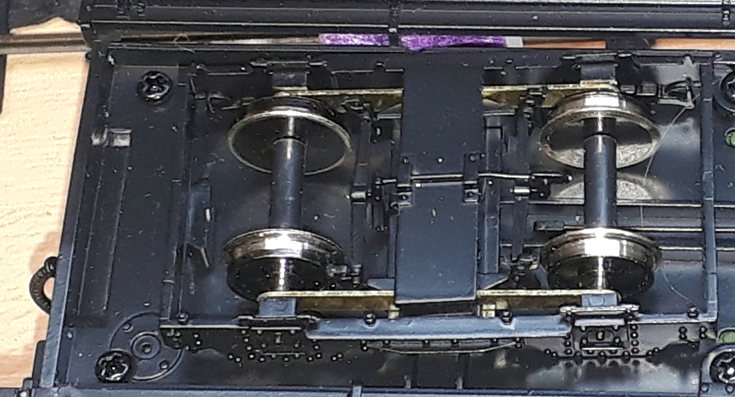 With the wheelsets done they can go back in the coaches.
Next job is plodding through the queue of coaches to be done and then there are 30+ loco’s to do.
This is a bit of a one shot production line. It may get repeated but it doesn’t really make economic sense to do it for a single coach so if there does need to be a second batch it will probably have to wait until there are several sets to do.
