Its been awhile since I did a blog post but things have been progressing with the NG7-14 version of the Bachmann Quarry Hunslet locomotives. I was hoping to be doing a post that ended with a 14mm gauge loco running but the conversion is taking a bit longer than I had hoped but for good reasons.
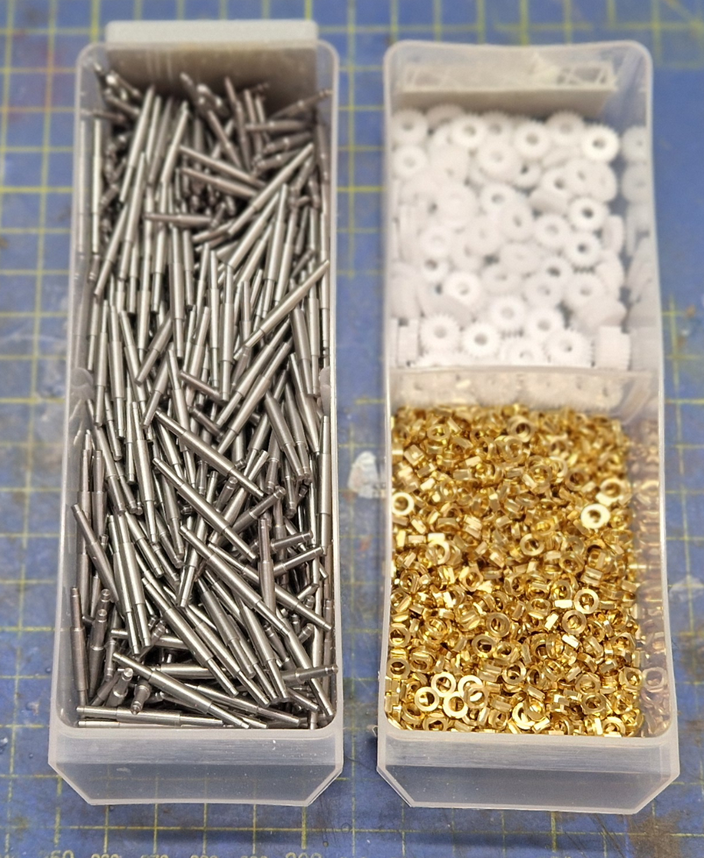
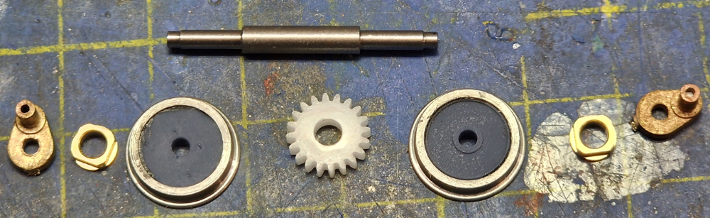
Axles, Bearings and Gears
We’ve started with the gathering of parts and since the last blog post the bearings have been changed from castings to machined parts.
Whilst the big gain for this project of using CNC machined parts is consistency of manufacture price also comes into it. As a rule of thumb if you are having something made by CNC machining the more you have the less they cost each. As an example lets take the axles
- 100 off = £1.50 each
- 200 off = £0.90 each
- 500 off = £0.50 each
An order for five hundred was a “no brainer” and these and the associated bearings will now form a standard in upcoming new kits and old kit upgrades. [nearly added “going forward” but that’s management speak for padding low content sentences]. That’s the first bit of the good element of things taking a little longer.
 If I were converting just one or two loco’s to 14mm gauge I’d probably wing it but with a quantity to do and the same parts now standard across my future range the making some tools to aid the production make a lot of sense and that is what is taking a bit of time now for a pay off in the long run.
Its got a lot to do with the repetitive consistency I keep going on about but with the second tool that’s going to get a mention its about not breaking drills and taps.
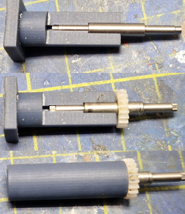
The first tool is about getting the gear on the axle in the right place. This is a printed tool and I first produced a sectioned one so as to be able to see what goes on inside.
Hopefully you can see that the axle is stopped in position by a shoulder in the bore and then the gear is pressed on as far as the flat end placing the gear on the axle. The pressing is done using my desktop lathe to ensure it all goes together true.
Cranks & Crankpins
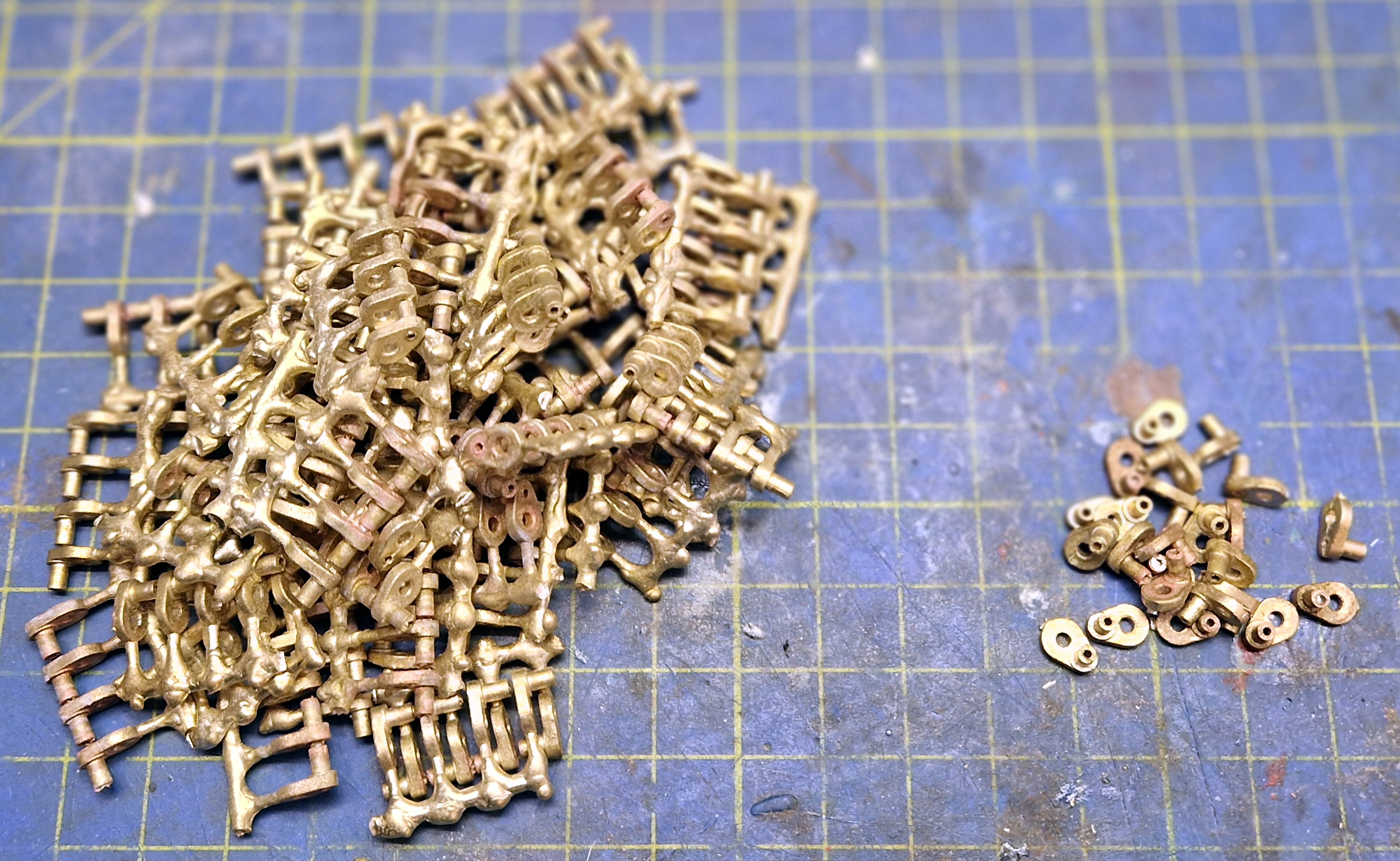
Next we come to the cranks. These are castings and they come on a sprue of four. Each needs the following actions
- Separate from the sprue
- Ream the axle hole
- Tidy the casting sprue stub
- Drill the crankpin hole
- Tap the crank pin hole
- Shorten half the cranks (leading axle)
I mentioned winging it if there were only a few to do but that most likely wouldn’t ensure the ream hole was perpendicular to the crank, would most likely snap several drills and the expensive tap. Filing each casting stub would be pretty tedious too.
Some tools are needed.
First up is a holding fixture to hold the crankpin casting whilst it gets drilled, reamed and tapped. Out with the CAD.
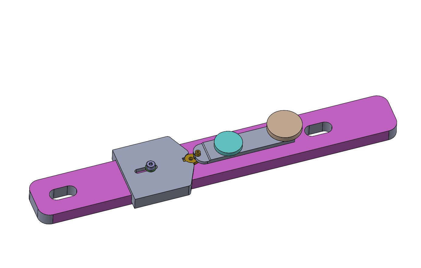
This is what I came up with. The violet bit is the base. The left hand grey bit holds the crank central and the bits on the right mimic a tool makers clamp to hold it down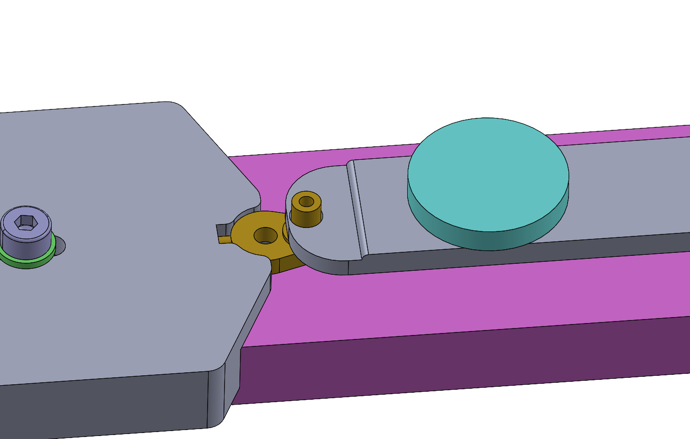
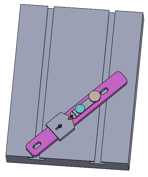
The idea is that this clamps to the bed of either my mini drill or tapping fixture thus
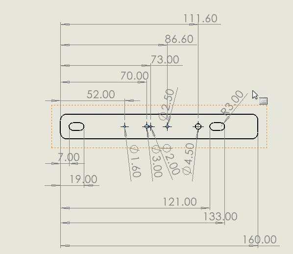 Time to get the old tools out. This is where the two workshop confusion starts. I have a downstairs workshop where the heavier engineering tools, the big lathe, 3D printers etc live and the upstairs model room where the small electric trains and the associated tools live.
 This picture represents an incursion of downstairs tools upstairs and will probably lead to cries of “where’s my – – – – – – – “ * when I can’t find something.
* insert name of missing thing
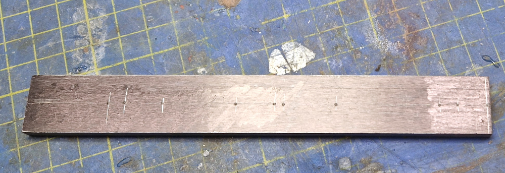
What we have here are odd leg callipers to mark the centreline, dividers to strike off the hole positions, an optical centre punch to punch the hole positions and a bit of ground gauge plate as the victim.
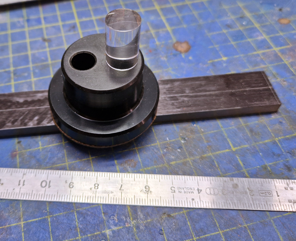 The optical centre punch is one of those expensive, hard to justify at the time, used once in a blue moon tools that once you’ve stumped up circa seventy quid you wonder how you ever managed without it.
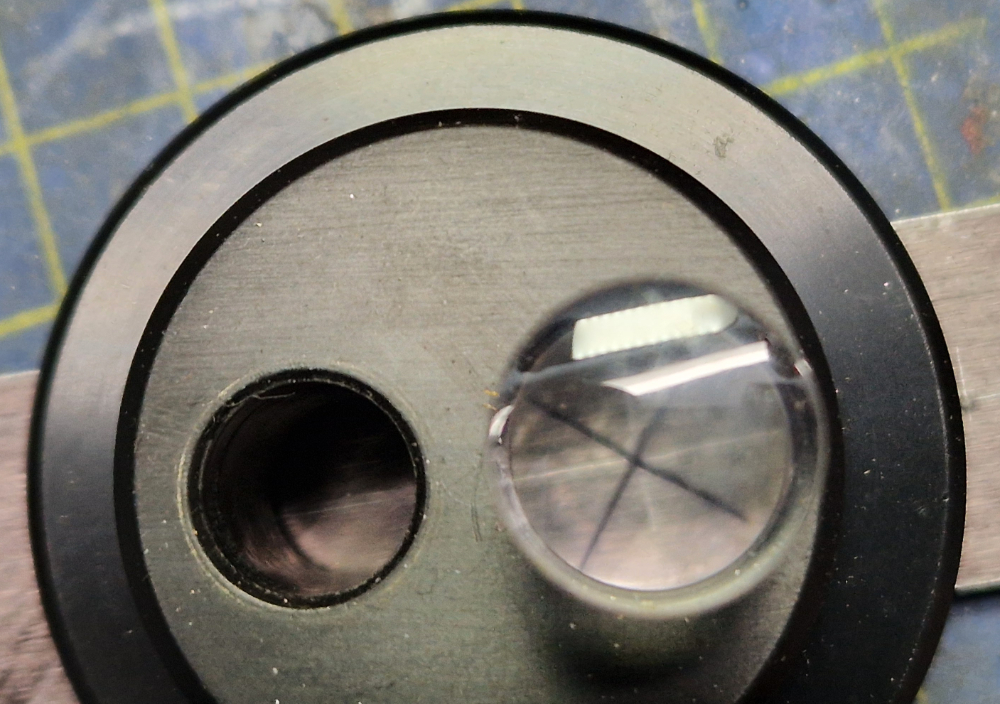 With a magnifying lens in the base you can line the cross hairs up on the scribe lines and then, holding tight, swap the lens for the punch and give it a clout.
Of course the posh way to mark it out would be to put it in the mill, find the centreline and then use the Digital Read Out to move to each position and drill the hole. My desktop mill can’t do that.
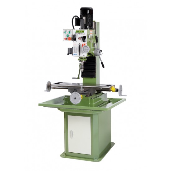
Anyone got one of these they don’t want or would like to store in my workshop?
So this episode closes with the base of the universal crankpin processing tool pop marked and ready for drilling and all the parts for the new wheelsets to hand.
 |
 |
More in the next thrilling episode of, “why do I take these jobs on”
