In the last episode we got as far as hiving made template in a photo package – I use Affinity. Now to prepare a base to build them on.
Firstly they were laid out on a sheet of 2mm ply to mark it and cut it to size. A thin, 0.4mm I think, layer of ply was added where the ties for the non moving parts of each turnout was added. This is done because the moving parts run on etched baseplates making them higher than on plain ties so the rest has to be lifted by that amount.
I then got a base of 10mm ply that would remain rigid whilst the turnouts were built. This was covered with a layer of 5mm foamboard so that any drillings that went though the turnout base went into something soft. The turnout bases were then fastened to the build board using a trick I saw in a guitar building You Tube channel. Both the underside of the turnout base and the top of the foam board were covered in blue painters tape. One then had blobs of thick cyanoacrylate glue applied whilst the other was sprayed with accelerator. They’re then pressed together to hold them. The theory is that when you want them apart the tape just peels. We’ll see as I’ve stuck spikes through it!
York Model Railway Exhibition was fast approaching and this was to be my show demo build so emphasis turned to making parts in prep that would be difficult at the show.
First up were crossing vees as I wanted these to be silver soldered to make them both rigid and impervious to later soft soldering activity.
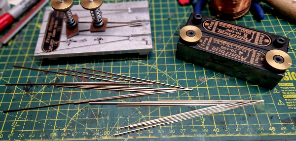
The jig is a Fast Tracks “Frog Helper” to which I have added the clamps. I think that the intent is that for soft soldering fingers hold it safely enough but as I was planning on pointing a blow torch at it and getting the rail red hot I thought clamps would be better than fingers.
I needed three #5’s and one #4 but I made several spares of each. They were filed using the Fats Tracks Pointform tool.
These come with Allen Screws as seen on the back one but I have done a mod to add thumbwheels as I can never find the Allen Key.
Next bright idea was these printed jigs hold all the bits for a point frog in the right place upside down whilst some wires were soldered across to hold it all together. There’s two, one for #5’s and one for #4’s
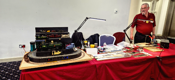
At the show three of us had a table on the top floor with a display of different scale narrow gauge modes and we were variously building track, wagons and coaches.
The show is a three day affair and is very convivial both at the show and at the after hours relaxing which may have been in a pub.
Turnout work commenced by making up the frogs and then laying them out over the plans. Ties were then added on to the plan adjusted to miss any of the wires holding the frog together.
There is now a bit of a gap in photo coverage as on day two at the show I had forgotten my phone (aka camera) whilst on day three I forgot.
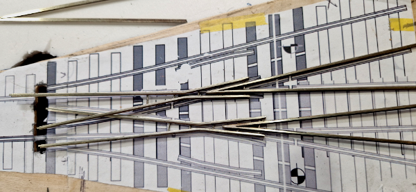
The rough summery is that the frogs were laid on the plan and cut to make the combined or leading crossing. There is probably science that could be applied but it was mostly guessing and estimating. Once happy that vee was soft soldered and the entire unit glued down to the ties using track gauges. With that done other rails were added using the track gauges.
Show now over and back at home I was keen to crack on now with all the tools to hand and with my camera handy.
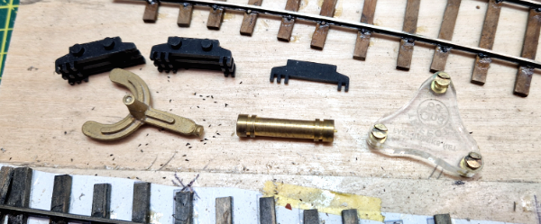
This is part of my collection of track gauges some bought and some 3D printed. The best “standard” is the Perspex one, this gets used where gauge is critical. The roller gauge is a bit naff as its too small in diameter and the grooves aren’t deep enough. Some of the printed ones also feature fixtures to hold check rails in place.
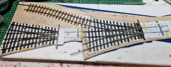
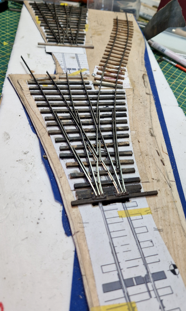
Eventually that got all the fixed rails in place. At this point they are only glued down. That said having wanted to move a rail I can say they are stuck in place and aren’t going anywhere.
They are glued with aliphatic glue applied by a pipette nozzle fitted to the bottle. This wicks in under the rail and as it starts to go off surplus can be removed with a wet paintbrush.
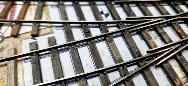
The rails are now fully spiked as well as glued.
They actually aren’t “spiked” as such as they are pushed into drilled holes and then glued by brushing the aliphatic glue on, leaving it for a couple of minutes whilst it wicks around the spike and down the hole then wiping/wicking any surplus off with a wet paintbrush.
Surplus glue leaves a shiny mark on the ties but a whizz over with a nylon brush in a rotary tool removes it. Final job for this chapter was to cut the rails for insulation gaps between each of the sections
The next instalment will cover making the moving parts, jigs to attach the operating wires and some cosmetics. I’m still thinking about the jigs design






 coming soon