Hopton (cont’d#1)

Hopton (For Carsington) – Henmore Dale Light Railway.

Having introduced Hopton by describing the previous layouts and, to some extent, what was wrong with them and explained the hiatus and, in my opinion, beneficial pause we come to the new layout and how we arrived at the current cunning plan. I ought to have got Andy to write this bit as after around a year of ZOOM and Messenger chats he put together a document that summarised what we had discussed and laid out some options and I am now going pick and choose from that.

  • A more compact layout which we can erect without needing a large hall.
  • A couple of cars to go to a show rather than a rented van.
  • Skill Building. (Note 1)
  • Manageable Start. If that is a success, then we build something else.
  • Presentation: To include backscene and lighting.
  • Coherent loco and rolling stock policy when exhibiting the layout. (Note 2)

A couple of those bullet points have notes attached as whilst we know what we mean they need a bit of amplification for the wider audience.

(Note 1): One failure of the old layout was in it progressing as our skills developed. Rather than a clean break, or update what we’d done, we’d build a new bit to our current standards/finance and life with the poor bits. Whilst what I call the poor bits were exhibitable there was a lack of consistency across the full layout.

(Note 2): We decided that, when exhibiting, the locomotives and stock on the layout should show some sort of a credible policy. The likes of the Welshpool and Leek and Manifold managed all their lives with two loco’s each and they matched their stock well. As an exhibition layout we’re always going to have more that two loco’s but in the past there was almost a competition to build the most outrageous. Then, on the layout unlikely combinations would run. Things like, for example, the full stone train with a Porter on the front when the last time it appeared in the sequence the same train needed an, equally ridiculous, 0-10-0 to pull it.
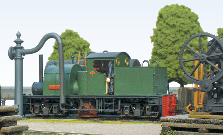
This credibility note has the proviso we can run all the silly stuff at home.
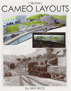
In a parallel universe Andy and I had copies of Creating Cameo Layouts by Iain Rice and had been discussing our own projects using the cameo idea. My own 0n3 layout started out in my head as a room sized project but has, with practicality applied, become a series of connected cameos (Ok, I’m still on the first one and its not connected to anything yet). What appeals is the self-contained nature with the pelmet top with lighting built in completing the presentation.

If, like me, you’ve read a lot of Iain Rice’s articles over the years you’ll have noticed him banging on about the proscenium arch idea stolen from theatre stage sets and used to focus the eye on the stage. The full cameo layout idea, and the book, is really the ultimate development of that theory.

The Route
When the definitive history of the HDLR is written it will surely detail all the considerations, meetings and minutes in account of estimation of traffic along the route but for now here is just a précis of the route and traffic.

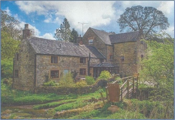
Atlow Mill – then

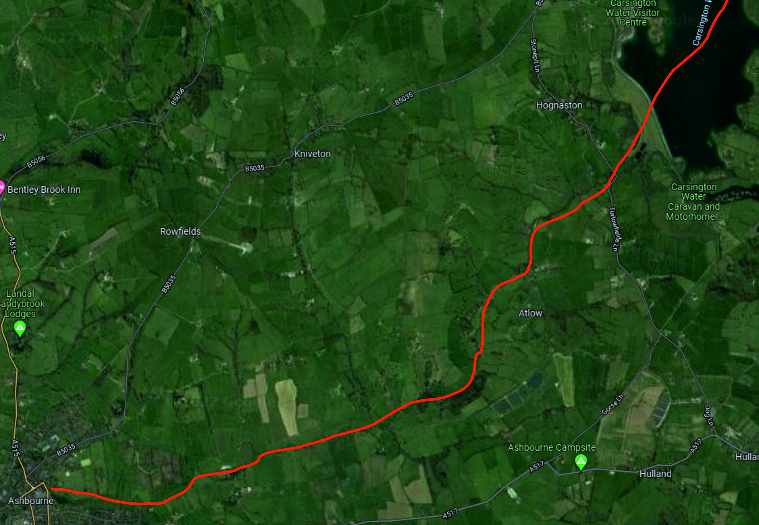
The modern map above shows as well as it can that the line heads east and then north east following the course of the Henmore Brook. In Ashbourne the railway had its own terminus but also squeezed through town to interchange at the North Staffordshire Railway Station. Leaving town past the railways own engineering base the line ran along the river to Hognaston station and thence to Atlow Mill having passed a timber yard and creamery on the way. From there the line climbed another three miles to Hopton and the quarries with some short branches to individual quarries.
Atlow Mill – Now

As you can see from the modern map the top end of the line is now under the Carsington Water reservoir that was built in the 1980’s and completed in 1992. It is now a popular leisure site for walking, cycling, fishing and water sports. If the HDLR Preservation Society ever get their act together a deviation towards the visitor centre would be a must.


Railway Traffic Assessment

Goods Traffic – Ashbourne to Hopton.

  • General Goods.
  • Farming Supplies e.g. fertiliser. Were there private stores for local farmer’s co-operative provided at HDLR stations?
  • Coal to all locations.
  • Empty churns.

Goods Traffic – Hopton to Ashbourne.

  • Full churns.
  • Flour from Sturston & Atlow Mills.
  • Logs to the saw mill at Ashbourne.
  • Stone from the quarries.

Passenger Traffic.

In addition to the daily passenger service. Market Day specials could be run bringing people into Ashbourne and Bank Holiday specials taking the residents of Ashbourne out into the Dale. Plus of course the Shrovetide Football specials.

Back to some modelling.

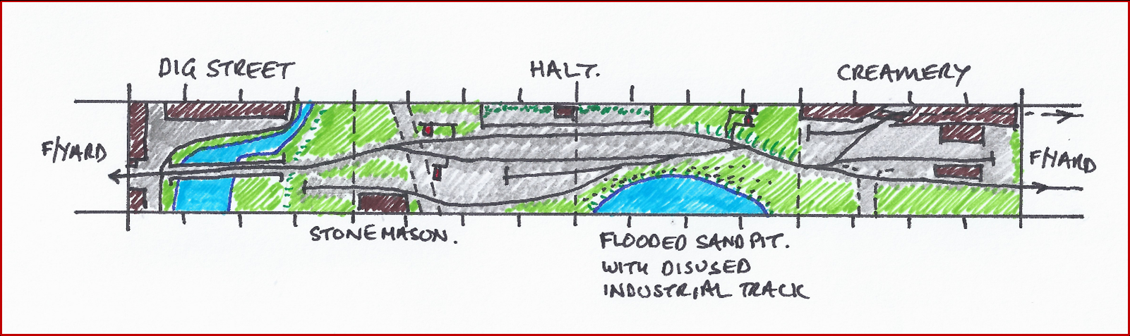
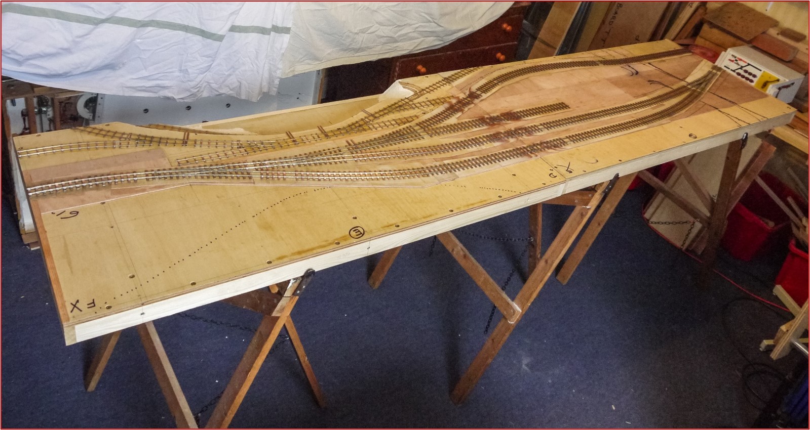
Having read up on the history (aka written it) the potential sites were discussed in the various zoom & messenger meetings and it was decided to model the end of the line at Hopton with a branch, joining at an inconvenient angle (aka operationally interesting) and some back and forth with options arrived at a plan.
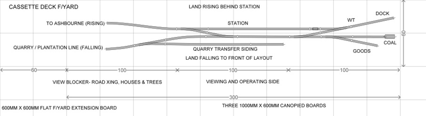
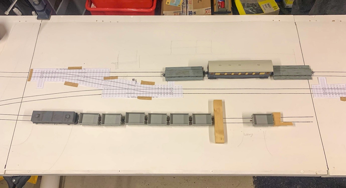
There followed some full size planning with templates and mock ups in the new modelling centre on plain wallpaper and some old boards.

Options were explored  and a few changes made to the plan.

Early on we decided that we didn’t like the flat baseboard layout and wanted some subtle changes in height.

The front edge of the layout will be cut away to give a lower level roadway and to facilitate gravity drops from rail to road. This road slopes up to and then crosses the railway to the left of the station.

The mainline to the rear and quarry line to the fore in the plan had the main line level and the quarry line falling but in planning this was changed to the quarry line climbs whilst the main line falls. Both grades are small but the two being adjacent will emphasise the difference and thus the quarry line helps hide the transition to the fiddle yard of the main line.

With a plan agreed it was time to crack on with some baseboards.

Loading

Hopton (For Carsington)

Hopton (For Carsington) – Henmore Dale Light Railway.

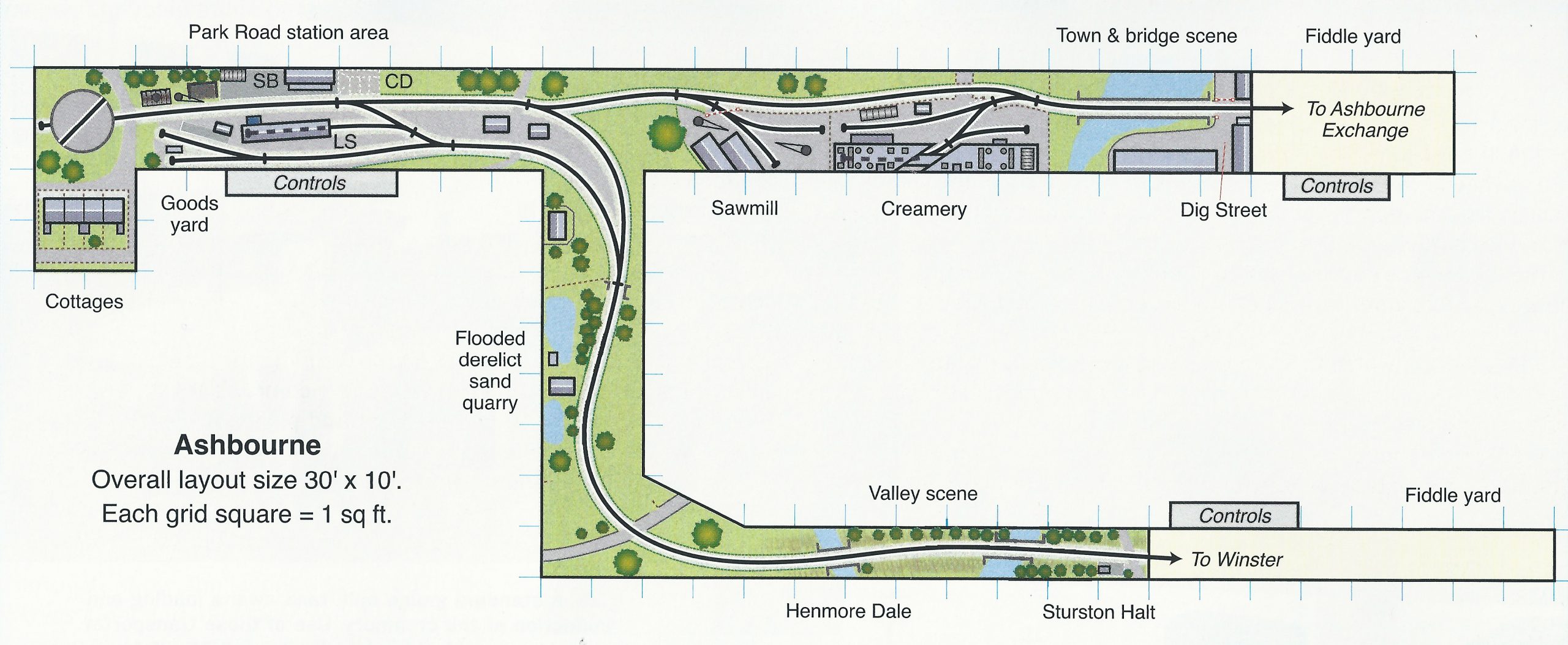
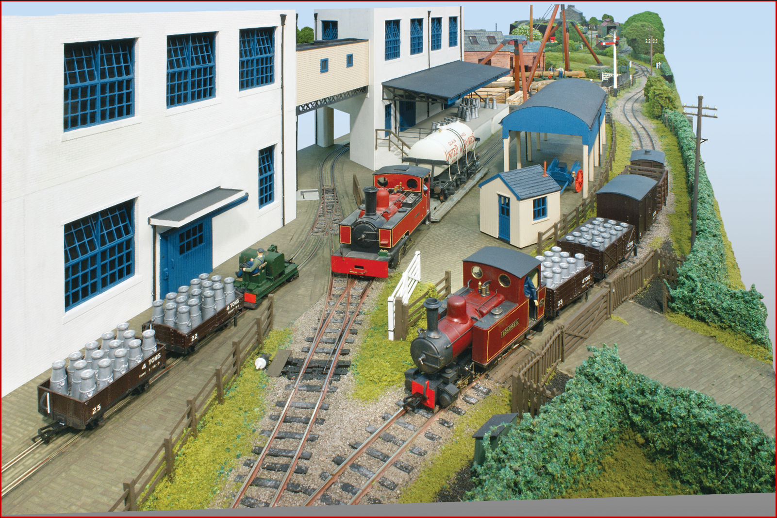
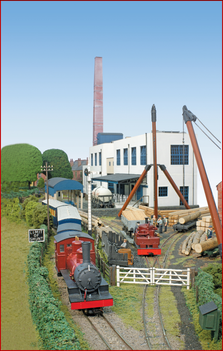
Those with decent memories will remember the Henmore Dale Light Railway of old. The HDLR is a might have been 2ft gauge line that ran from a standard gauge interchange in the town of Ashbourne in a generally easterly direction along the valley of the Henmore Brook towards the same stone quarries that the Cromford & High Peak served. Along the way it served a creamery and a saw mill. Now the top end of the line would be under Carsington Water.

That’s the fiction.

The HDLR was the group layout of the Trent Valley Group of the 7mm NGA and was started, using second hand boards, as focus for the group. It grew a bit like topsy and was the origin of the TVG Open Days as we had to rent a hall to be able to put the whole layout up.

It grew as our standard of modelling improved. The Ashbourne Park Road area used second hand chipboard base boards and reclaimed track. First it extended towards Ashbourne exchange and then the other leg towards Winster by which time it was using lightweight boards and hand laid track.

We last exhibited this layout at York in 2013 (just looking that up and finding how long ago it was came as a shock).

Troubles

I’ve thought a lot about whether to include this next bit or to just gloss over it but in the end I think some understanding of it its required to see the story develop.

So far I mentioned that it all got a bit big and unwieldy. What needs adding to that is a growing dissatisfaction with the layouts mixed standards. The newer bits were fine scale but the stock still had to run over the early bits and the Park Road base boards were showing their age.

Following that show personalities came to the fore and the group dynamic became awkward. One of stalwarts of the group was Tim Allsopp who, unable to work on medical grounds, both stored the layout and did lots to it. I am very wary of writing this as he’s no longer here to defend himself but the layout was more and more becoming Tim’s layout with less and less input from the group. Time would tend to do it his way, If you had a good idea he’d tell you it wouldn’t work and then have the same idea a week later and if he didn’t like your suggestion he’d just ignore it. It was an attitude that risked splitting the group up.

Sandy Lane Halt – Henmore Dale Light Railway

There followed a summit meeting where all expressed their views and a new way of working was agreed and a new layout started. This was to be the next chapter in the Henmore Saga and be a simple model of a halt further up the line.

Sadly, it wasn’t the cure we’d hoped and it wasn’t long before Tim reverted to type and the group just stopped working on it. We still met as a group and Tim was still a great friend, excellent modeller and an inspiration. We all just got on with our own things.

The dynamic really changed in 2018 when Tim was diagnosed with cancer and steadily declined. He was able to see the layout at its one appearance at the group open day in January 2019. Tim passed away in the July.

Much of Tim’s model stuff was left to the group with members acting as joint executors with his brother. The basic deal was take your pick, use what you can, flog what you can. The 2020 Open Day featured a sale of Tim’s stuff and a significant sum was raised which went to a cancer charity.

This all knocked the group for six and there had been no talk of layouts for ages then Covid hit.

Covid & the TVG.

Only a fool would suggest Covid was a good thing but in a world of predominantly unpleasant news there was an unexpected benefit – ZOOM.

The TVG used to meet monthly in the pub. Usually the Brunswick by Derby station. We used to have use of the boardroom so could bring and play with models whilst having a decent beer. The boardroom was redeveloped and whilst we’d kid ourselves it was a group meeting it was no different to meeting your mates down the pub with Tim in his usual spot leaning on the bar. It wasn’t convenient for the shift workers and the more distant members.

What happened with Covid was that the TVG met online using Zoom once a fortnight and we have continued to do that to this day. The format is much the same as a face to face meeting as we all get a beer and take the mick unmercifully but a bit of modelling gets done too. We’ve only missed something like three meets and those were when we were all doing something different on the zoom night. One member tried to restart the pub nights but it didn’t catch on.

As part of clearing all the stuff from Tim’s a members garage became the store and has now developed into a modelling space (albeit a bit too chilly just now). As the covid thing eased a few practical working meetings have been held that have further sorted the Tim’s stuff archive and to strip some of the remaining bits of the old layout for usable parts before consigning it to the tip.

On zoom the group discussed what a new layout would be like if we built one and this refined itself to when we built one and now we’ve started.

Hopton (For Carsington) – Henmore Dale Light Railway is born.

With bucket loads of hindsight Tim’s demise was a shock that hit us all. Dealing with that and the interlude forced by Covid provided the break the group needed to put the old aside and come back with fresh ideas. Without it, we’d probably not have got round to doing anything.

The first bits of the new layout will be at the TVG Members Day in Mickleover, Derby on the 28th of January 2023.

The next instalment will, finally, get on to the new layout.


Loading

The Brymston RR #25- Vandalism?

CONSIDERING AN ACT OF VANDALISM!

Earlier we were discussing the loco shed for the Brymston RR and I made a mock up of something in card. It’s gone not further than that until just now….

I was sat in the stores packing customers orders and having a moment of idly staring in to space waiting for the printer to get its act together when I spied a box on the top shelf. Intrigued I got it down.

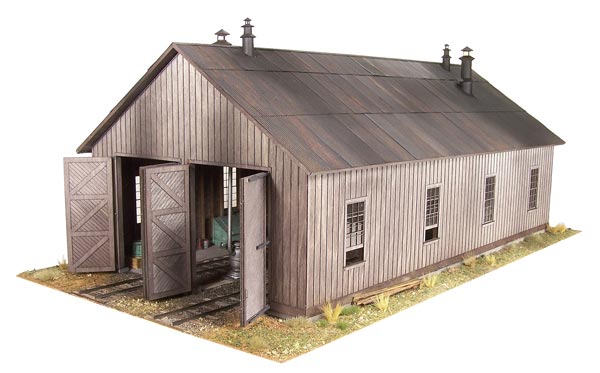
It was a kit for a loco shed. Not quite what I want but it could work with mods

OUEOMain.jpg

The act of vandalism?

It’s a Raggs to Riches kit for Ouray Engine House.  Raggs kits are the mutts nuts both in terms of buildability and accuracy and they’re no longer available Raggs having retired.

Modifying this kit would probably be the model equivalent of putting a UPVC conservatory on a grade 1 listed building.

Loading

Brymston RR– #24–Bendy Engine Progress

In odd moments I have been progressing the sorting out of one of the bendy engines. In the first episode about this bendy engine I dismantled the front truck and reduced it to it component parts. “Off Camera” as it were, the parts have been cleaned and sprayed with an etching primer ready for reassembly.

First move was to establish some polarities to be sure I put the wheels in the right way round. Tradition on American brass models is to have wheelsets insulated on one side only so the other side conducts to the frame. Then, on a tender engine, the tender is live to one rail and the loco to the other. You can see the problem here – no tender.

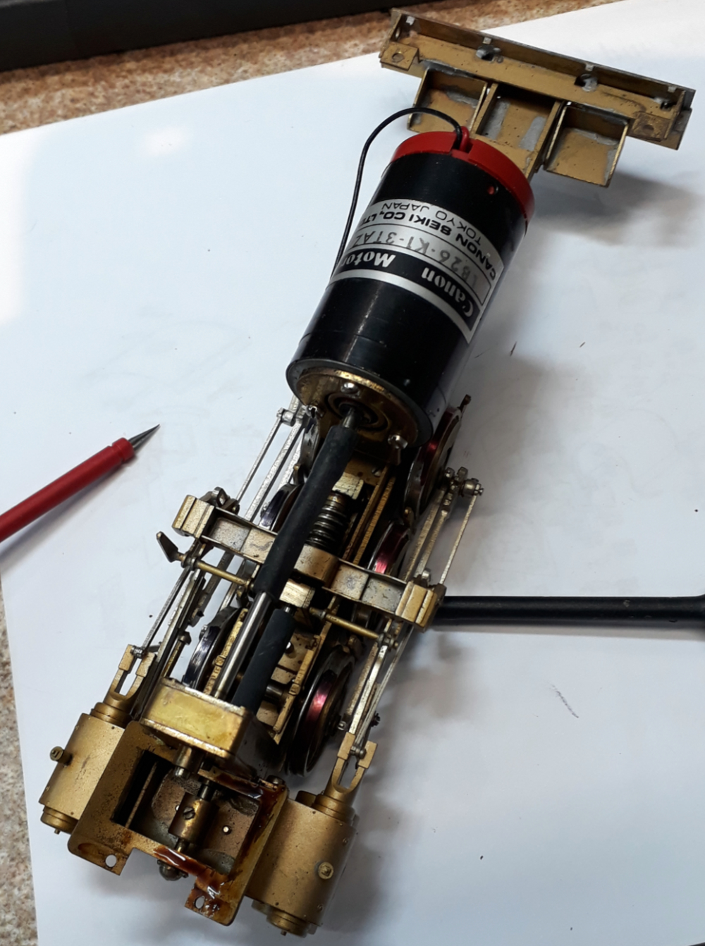
On this loco, being a Mallet there is a fixed power unit and an articulated one. The fixed unit has one side live to the frame and wiper pickups to the insulated side and then on the articulated truck just one side live to the rail. So its got 3 wheel pickup to one rail and six wheel pickup to the other rail. I intend to add wipers to the articulated end but for now I just need to make sure the wheels live to the frame on both are on the same side.

This was done with a multi-meter on its continuity (beep) setting. PANIC. It beeped to both sides! For now I went with the wipers as a clue and resolved to sort the potential issue out when it was the rear bits turn for overhaul.

Using the beep test the live wheel was identified with red marker pen and then assembled into the frame. I WISH IT HAD BEEN THAT EASY!  The driving wheels are sprung and, unusually for American brass they actually work. Usually you’ll see a coil spring above each axle box that is so strong it does nothing other than press the wheel hard against the keep. This has wire longitudinal springs that hook behind two pins on each side and then bear against the axle bearings. Neat when together but I used up a lot of fitters language getting them in.

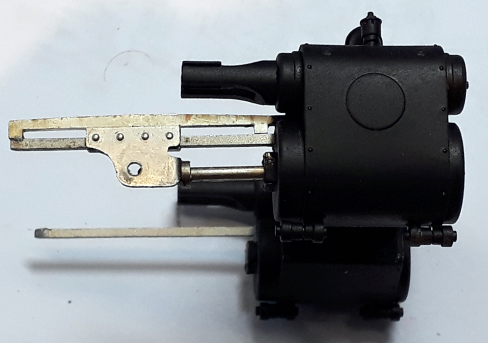
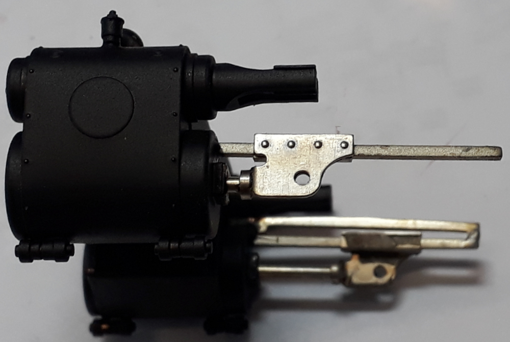
Next to add would have been the cylinders but here I found a problem. This first picture is how they should look with the guide bar above the slidebar and with the rear end keeping the crosshead captive.

The clue that something was amiss was the crosshead falling out of the other side. Looks like tomorrow mornings task involves whittling some nickel silver fret offcuts to shape.

Finally for this small work session I decided to have a look at the fixed power unit and disconnected the motor. A retest of the wheel insulation revealed there to be no problem. The beep to both sides was because the fancy Canon motor is such low resistance that there was a path through the motor from the insulated wheels.  Some power to the motor wires had it all running. It has a small squeak once per revolution and its seems tight. There’s some dubious looking oil oozing out of the spur gear box but that will all get cleaned out when this bit get overhauled

Coming soon


Loading

Brymston RR #23 Moving Mountains

I do like it when a plan comes together.

This is what all the mess in the dirty stuff workshop has been about. The two boards that are currently the Brymston Railroad are joined together and the mountain back scene is all mounted and in place and, at least from this angle, you can’t see the join.

The join is a bit more obvious when looking from this angle but I have a plan – maybe. It all looks a lot better just from the reduction in the amount of bright white primer there is on show.

The backscenes are adhesive backed vinyl and, were I doing it again, I’m not sure I’d get the adhesive backed ones again. The instant tack and a desire to stick to anything and everything barring where you want it too made getting them smooth difficult but then it wouldn’t stick at the edges.

I think a PVA giving more adjustment time would be better. I’ve had to glue the edges with a vinyl glue and tape them with low tack tape and once that’s hard I plan several layers of acrylic varnish to build up a hard edge.

Shortly the long board will go back upstairs to the model room whilst the corner board will get more foam added to build up the mountains, the tunnel mouth added and the track ballasted keeping the messy stuff downstairs. I do need to get myself a freehand hot knife foam cutter.

The cunning plan for the join is a half relief tree with its first branches high enough to let a train past and with its top somewhere in the clouds but that will be a late addition as I don’t fancy tree making.

As the layout develops the scenery and buildings will slowly hide the mountain backscene so its glimpsed through the structures, trains and trees and will merge, well, into the background.

The corner board and the fiddle board need a bit of engineering to mate them as they weren’t intended for each other. The fiddle board may just be temporary as its been repurposed from another stalled project.


Loading

BRYMSTON RR-#22-SNOOKERED!

Can you see an abrasive blaster in this image?

I’ve snookered myself with two ongoing projects. In the image you can see the backscene project waiting for filler to harden in a room that could do with being a bit warmer. It’s all still a bit too soft to risk moving any of it. More on boards soon.

Onward then with the bendy engine project.

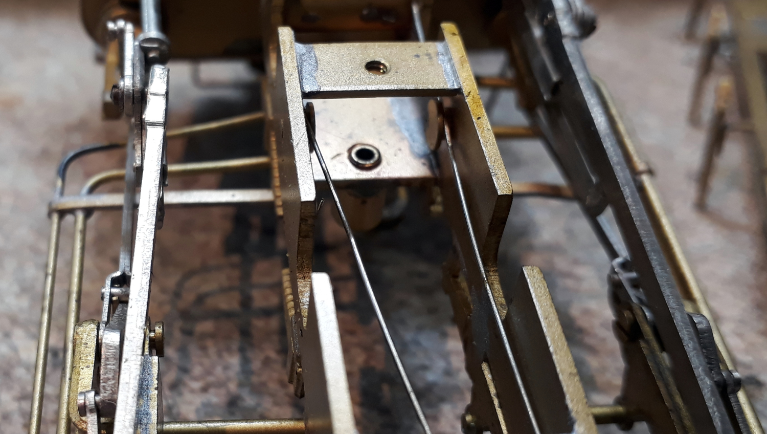
So, we had displaced springy things and disconnected U/J’s but the root of the problem is this piece of pipe detail.

One end screws to the power bogie allowing it to swivel side to side with a small amount of up and down permitted. The other end slides in a slot in the underside of the smokebox so it can slide along the slot as the bogie swivels.

The pipe is inserted in the slot at one end as its shaped like a keyhole. Its supposed to limit the amount the bogie can drop if picked up by the body.

It didn’t which is why the sprung bearing got out and the UJ undid.

The problem can be seen in the pipe image above. The smokebox slides between the two washers so it the right hand (top) one that has to support the weight and its too twee and has bent.


When in place it should look like this.


The plan to fix it?

First job is to flatten the bent washer and of that I’ve turned a bit of brass with a hole up the middle to make a small anvil/press tool. I’m hoping a few light taps will flatten the bent washer.

A new turned washer that it s bit thicker will then be soldered to the back of the bent washer to reinforce it.

The abrasive blast cabinet?  These models often had some impenetrable lacquer applied and there is other paint and contamination on the part so my plan was to give it a rough time in the blaster so I am at least trying to solder to clean brass. Its whereabouts? Behind all the boards I can’t move for awhile.

Coming Soon

Loading

BRYMSTON RR – #21 – BENDY ENGINE BOTHER

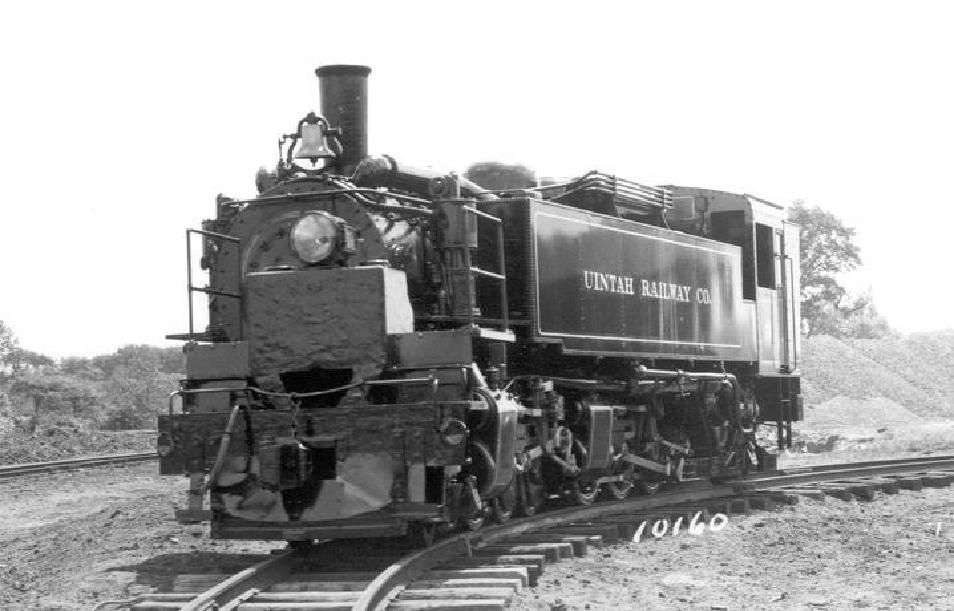
OK, in earlier episodes you’ve seen my Bendy Engine Uintah 2-6-6-2 Mallet checking the curves. I have two of these aiming to model both the Uintah engines.

One, the shiniest, did service on my sales display for many years ticking over on a rolling road. It went back in the display case due to a slipping drive shaft. In the medium term (its already past that) it’ll stay on display.

It’s the other one that’s been used for gauging trials and as I’ve just picked it up off the layout prior to moving the board to do what was to be the next instalment of the board saga the front power unit fell away and disconnected its drive shaft.


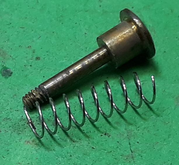
I also noticed that the sprung plunger that is supposed to transfer some weight from the body to the truck was trying to escape.

I thought popping that back in would be a five minute job. Boy have I opened a can of worms!


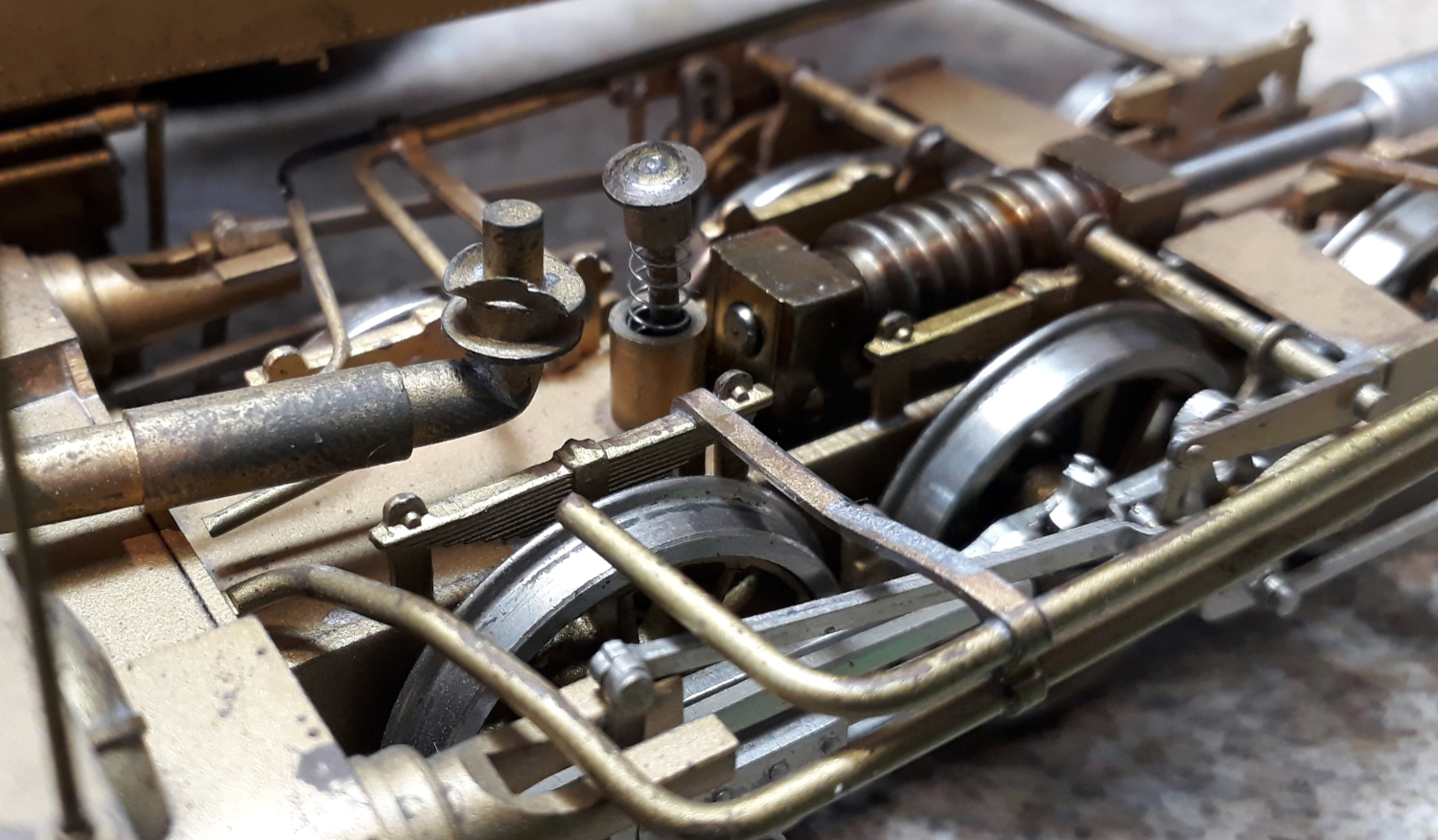
It should fit in here like this but a bit further in and retained by a nut underneath.


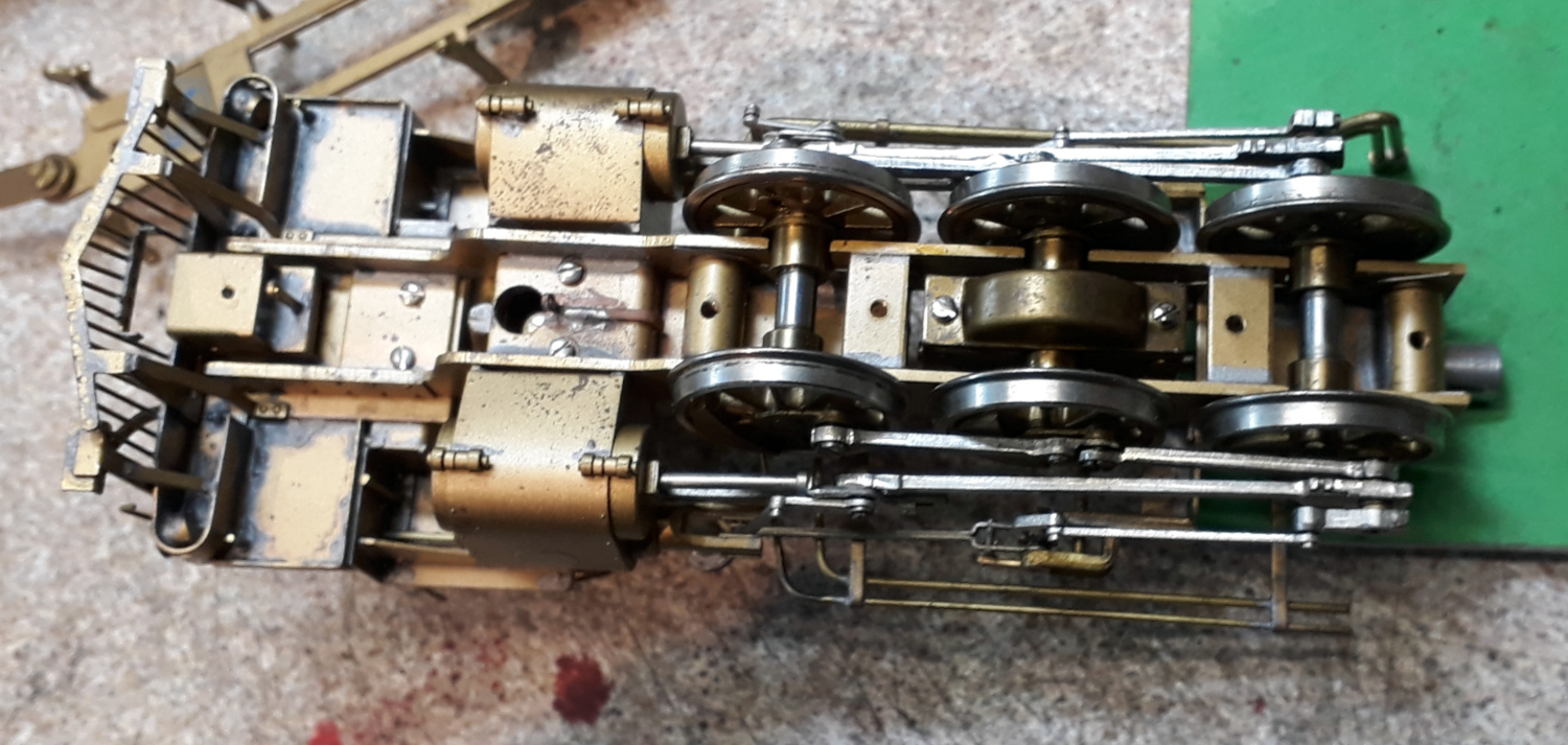
Removing the front power unit was easy by just undoing one screw. It went downhill from there. I thought “just pop the keeper plate off and put the retaining nut back on the plunger.


Nope! The bit we need access to is behind the stretcher and between the gearbox and the front axle.

The image to the right jumps ahead a bit but the plunger stem should pop through the lower hole and have a nut on it.


So, I thought, I’ll just undo the gearbox as it could probably do with a re-lube and drop the wheels out. It went downhill from there!

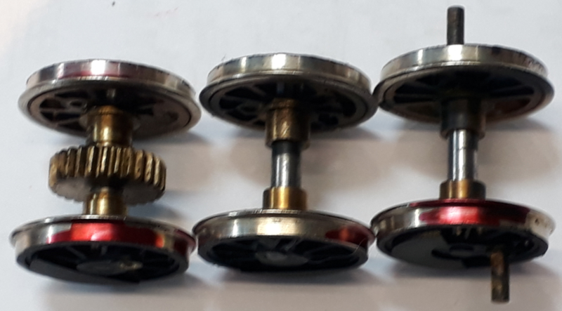
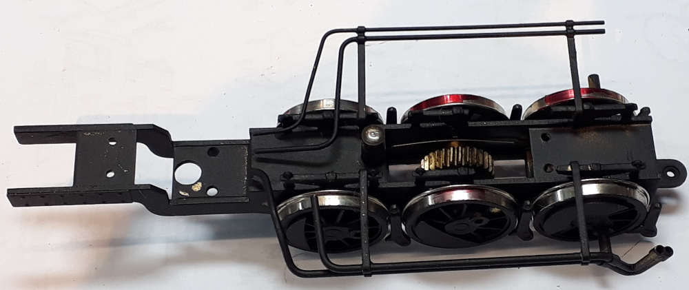
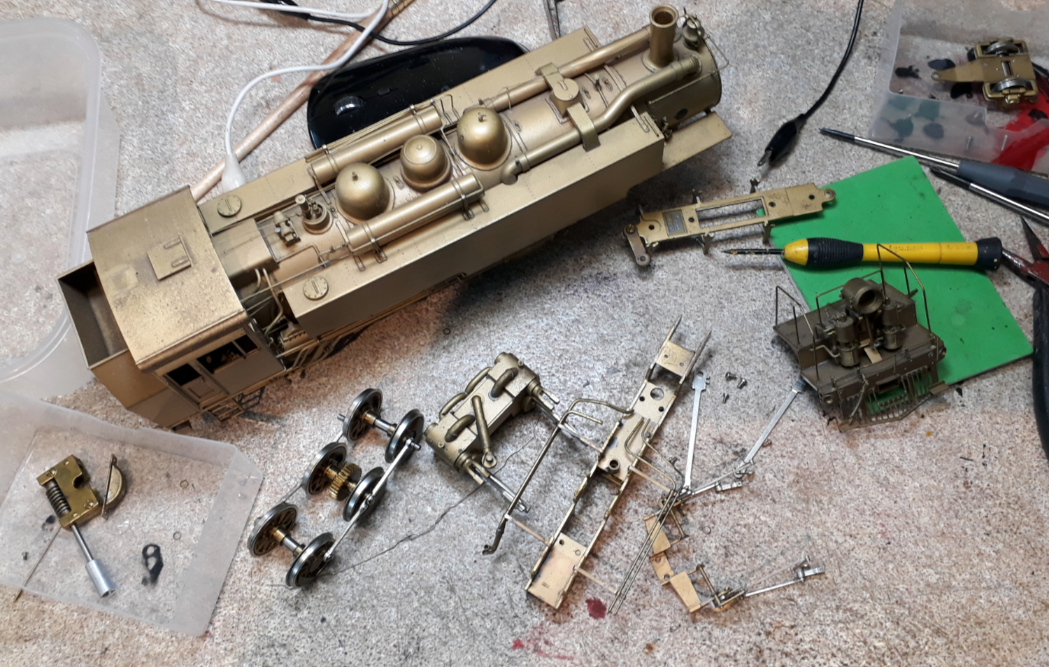
Having got so far with this dismantling now might be the time to start some of its paint job and upgrade whilst I am this far in so I went a bit mad and took the front truck as much to bits as possible.

An upgrade it needs doing are to add pickups to one side of its drivers and, if I can, to the front truck. You could argue this isn’t necessary as both sides of the rigid truck pickup and then bendy truck picks up through one side of the frames. Fitting keep a keep alive with its DCC sound install would avoid any stalling but I have two reasons for doing so.

  1. In my opinion even with a keep alive you can’t have too many pickups and,
  2. My layout uses DCC with position detection by sensing motor current and it’s a confined layout so this loco needs to trip the detection as it arrives at a point not after half the loco has passed the point.

The front headlight also needs converting from an ornament in to a working headlight which will mean drilling some holes and running some wires across the truck.

Almost inevitably I’ll follow this up with doing the fixed truck so it matches and I can address one of its Achilles heals. Most of the drive has universal joint but in the depths of the fixed truck there is one that is a bit of silicon tube and they’re prone to slipping on the shaft.

This episode was written whilst the trucks parts were drying following a swim in mu ultrasonic cleaner.

Coming Soon


Loading

BRYMSTON RR – #20 – MAKING A SCENE

Episode 20 in this flurry of writing should get the story up to the point the layout is at now but it won’t be the end for long as I have

  • Committed to taking all or some of the layout to Mickleover Members day in January
  • Found my Mojo for doing the layout and aim to keep going with it.

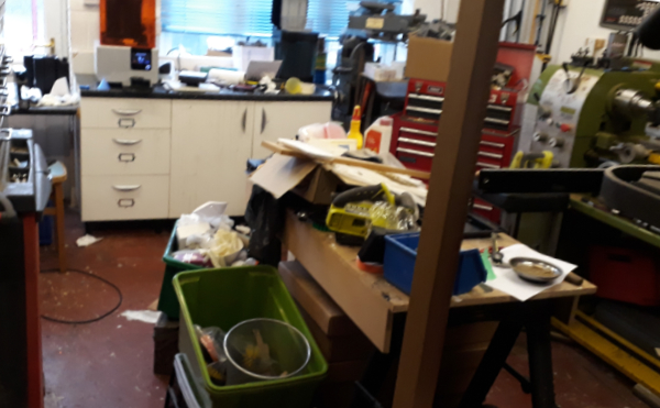
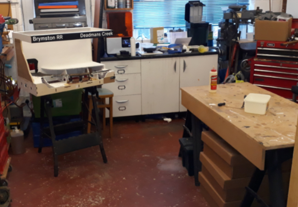
I am fortunate to have two work spaces. I have what would be the garage (if it had a garage door) downstairs and you might call this the heavy engineering workshop as it has my lathe, mill, drills, 3D printer, injection moulder and all manner of other tools. It’s the messy workshop.

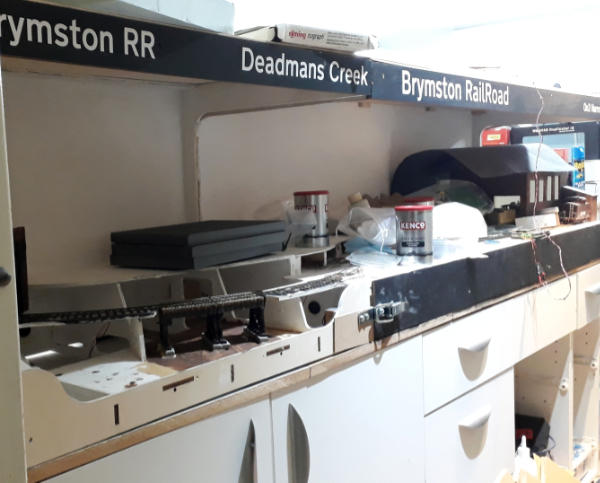
Upstairs I have my model room which management reliably informs me should be the master bedroom. I had visions of a large layout but EDM Models has most of the space in a room fitted out with kitchen units to make cupboard space and worktop. As explained earlier the realisation that the big layout wasn’t going to happen led to the modules idea and episode 10 had a diagram of where it sits in the room.

Both locations have a problem. In the messy workshop there is access off the kitchen and its way too easy to do the “where shall I put this” – “stuff it in the workshop”. It’s not helped by me not being very tidy natured and the 3D printer operating on the basis of actual prints being a by product of it making a mess!

Upstairs the layout offers a way to convenient shelf and nine months of inactivity had filled the shelf up. To be fair a lot of the clutter is actually layout making stuff but I have often joked about making the top cover a sloping top so I cant put stuff on it!

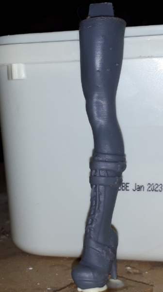
So, my modelling day started with a massive tidy up in both locations and took a good bit of the morning. The workshop now looks a lot better (with the help of selective photography). It is a constant surprise what you find. Anyone short of a leg

The reason for this tidy up in two locations is that this burst of modelling is going to be messy so the corner board of the layout needed to be in the downstairs workshop near the power tools.

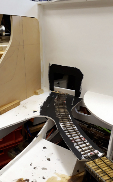
The aim of the game is to remove this sharp corner by fitting a curved backscene.

This is to be a sheet of flexi MDF and the bit of forward planning I alluded to was that I had purchased a sheet in advance. The idea is to avoid a sharp corner which is very difficult to scenic convincingly.

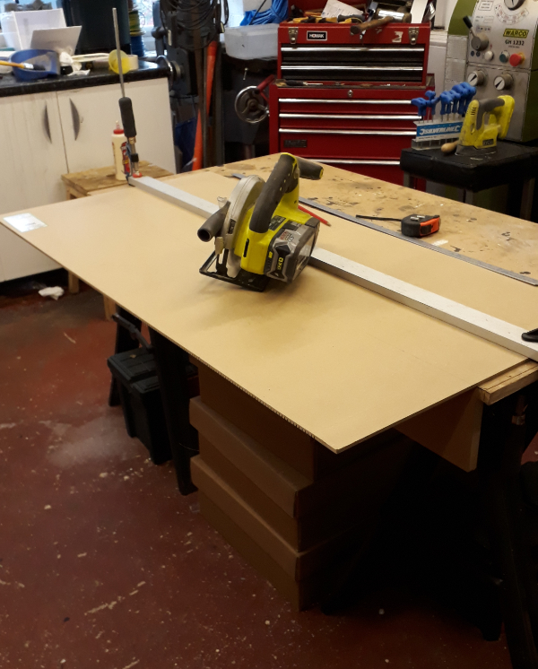
The first job, cutting it down to size, justified the move to the messy workshop as despite PPE, extraction on the saw the main product seemed to be dust!

The MDF was held down and my long cutting guide fitted to guide the circular saw. Despite lots of measuring and checking I always worry that I have got the guide offset wrong before cutting.

A coffee break was declared to let the dust settle.

Having got the height right the MDF was placed on the layout to get the length right and to cut the hole for the tunnel.

At this point there was an outbreak of bad language as the MDF instead of curving smoothly kinked as one of the grooves that make it flex split. This was repaired with a glued patch and something else was done for a while whilst it stuck. I also painted round the tunnel hole with wood working glue to seal the edges a bit.

Feeling my age interlude:

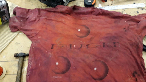
Whilst cleaning up I noticed the rag was an ancient T shirt

A Rush ‘ Hold Your Fire ‘ tour T shirt.

It doesn’t seem that long ago but it was April 1998 at the NEC I went to see them!

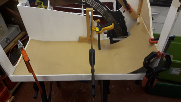
A wise man (I think it was Norm from the New Yankee Workshop) once said “There’s no such thing as too many clamps”. I agree and have deployed a fraction on mine here to hold the MDF backscene here whilst the glue dries.

If I remember rightly this was then end of day one and the glue was left to dry overnight and another baseboard project was got on with (more on that in another post soon).

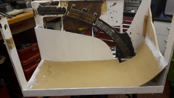
Next morning it was filler time to feather the edges. Plan A didn’t work, Who’d have thought that the two part epoxy filler that’s been in the cupboard for at least ten years would have gone off.

Luckily I had some flexible decorating filler to hand that hadn’t gone off. Its downside being that it took a lot longer to harden.

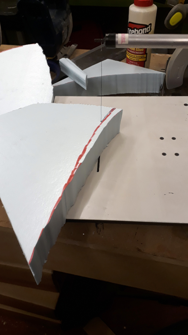
To pass the time I broke out the foam cutter. I use this about once every five years and every five years it reminds me of how crap it is but as I only use it so rarely I got justify getting a decent one.

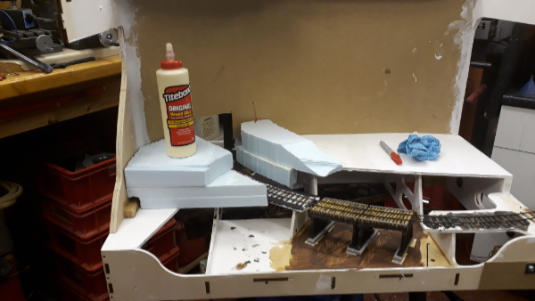
As I am aiming to keep the boards as light as possible the hills are to formed of dense foam blocks profiled to shape and glued together with PVA glue. This is another reason for being in the messy stuff workshop as this stuff goes everywhere.

The hills are starting to take shape. Next I need to find my hand held cutter (its had five years to hide) to shape them and to add the tunnel mouth mock up to position that in the contours. Once the rough contours are sorted it’ll all be covered in a hard shell coating (more mess).

That’s where we leave this episode. I have decided I like the back scene sheet idea and the other board will be getting a trip to the workshop for a similar treatment although it doesn’t have any of the tight corners on it.

[post views]

Loading