 As hinted at the end of the last update there is a change of subject for this one with developments on the corner board with a start made to create the hand laid track.
As is often my way I’ve made it complicated for myself but as the curve will be on the limit of minimum radius for some of the locos to go round it it I decided that I needed to ensure it was a constant curve with no kinks or tight bits in it.
It was also to be rail just glued into place initially with spikes added later so it was also important that the rail wasn’t trying to spring to straight.
I had two tools to help me sort this. One bought and the other designed and built by me.
 The first gadget is a rail bender which allowed me to pre-bend the rail to the right radius so it laid in place without trying to straighten. This was a commercial unit I bought years ago from the people that do the fast track jigs.
The second tool was a frame I designed and 3D printed to hold the rail at the correct radius for the inner rail of the curve and ensured it was a constant sweep through the curve. With it the rail was positioned over the ties glued down to the baseboard, weighted down and glued. It was left overnight to dry fully.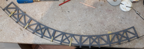
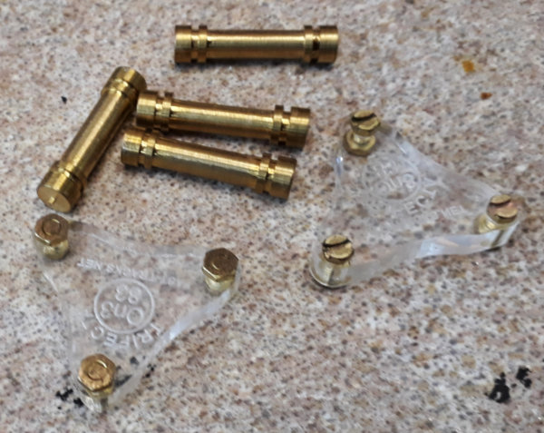 The second rail was added with the first still held in the printed frame. To do this I used two sorts of track gauges.
The first were roller gauges and the other were a pair of 3 point gauges. The way I did it was to hold the second rail along its length with the rollers but next to where is was soldering it – oops forgot to mention that amongst the wood ties were some PCB ones – I used the three points as this puts a little bit of gauge widening in to the outer rail. Not much but every little helps.
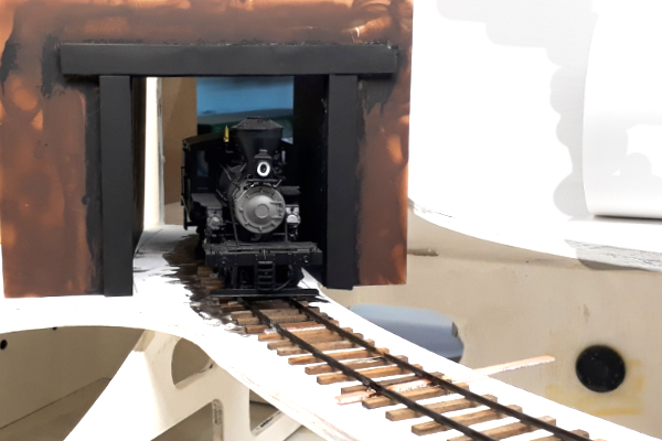
In the orgy of foam board mocking up the layout I also produced a tunnel mouth so you can begin to see what it should look like.
The next job was to cut a gap in the plywood where the bridge is to go.

The resultant gap needs a bridge
 First thought were of some sort of plate girder bridge as modelled here in foam board and with my Climax posing for scale.
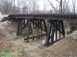
There was quite a lot of debate about bridges on one of the forums and in the end having been sent images like these I settled on a trestle
 |
 |
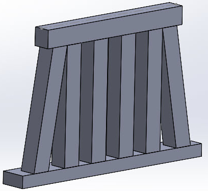
I sketched up some ideas in CAD. not detailed but enough to give me an idea
 |
|
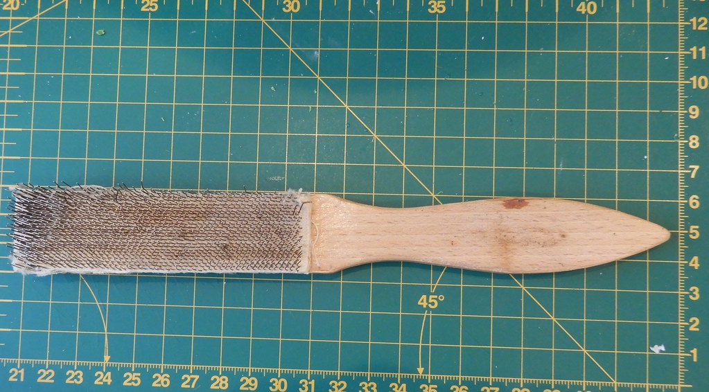
I had hoped to modify an Evergreen Hill Trestle kit I had but in the end it just became a source for the wood. That would was all a bit too regular so it got some abuse from a knife, wire brush and fire
 |
 |
 |
With the rails unsupported and vulnerable across the gap I was keen to get a bridge in place asap. The bridge was built temporarily on a bit of plywood and was initially designed to pin together with cocktail sticks.

On its bit of ply it could then be placed under the rails and the deck timbers placed in the correct alignment. At this point I was debating whether to do timbers under the rail but in the end decided against it.

Clearly the bridge was still too low but it needed some foundations for the piers. These were cast in DAS stone compound with a very crude jig and on cling film so as to able to get it out.

These foundations were cast a smidge too thick anticipating some shrinkage and left to dry. Once dried the bridge was packed up to touch the rails and the foundations sanded until they slipped into place with some packers. With them in place they were glued to the bridge and layout and the rails glued to the deck. A bit of weathering tidied it up and the track will get more when the adjacent sections have been ballasted.
 With the bridge in place and with the rail supported and protected by it towards the end of March progress pretty much fizzled out until the weekend just gone when work resumed on a different aspect which provides the ideal point at which to end this episode.
 |
[post views] |  |
