Castles Weren’t Built in day


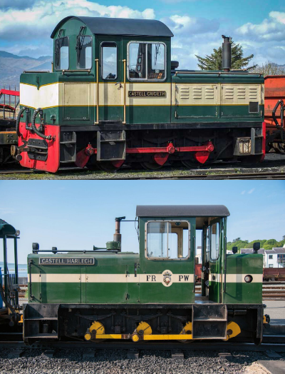
Harlech Castle

Criccieth Castle

Yes, they’re taking a lot longer than originally planned and it may be a month or two before they’re finally released: Why?

  • Considerable Spec Upgrade
  • Component Sourcing turning into component manufacturing
  • Mid project redesign to adopt the ungraded spec
  • Clashing with other commitments
  • Financing

These are explained a bit more below:

Spec Upgrade: At the outset this was going to be a simple chassis to use with the bodies blown up from 4mm prints. It very quickly got upgraded to newly designed bodies, sprung chassis, coreless motor and quartered axles and jackshaft

Component Manufacture: I’ll admit that with the demise of Markits (owner died) it hadn’t occurred to me that there would be a world shortage of crankpins. The solution was our first venture into Chinese manufacturing which was a significant capital outlay and was a bit scary the first time. We’ve been back to our Chinese manufacturer for more components.  

Redesign: Fourdees on sight of the first iteration of the chassis decided that blown up bodies wouldn’t do as they’d just be blowing up the compromises used to make the 4mm version work. The bodies are all new CAD artwork and my early visits to the Festiniog Railway included regularly visiting the prototypes to clarify measurements and details.

Clashing commitments: Regular subscribers to my newsletter and blog will know two things. 1) I am a volunteer driver on the Festiniog Railway and also the volunteer rolling stock electrical engineer. 2) I have achieved retirement age.  I’m not retiring bit it is changing things I do. I intend to do more driving whilst I am fit and able which impacts summer time available to model projects and I intend to progress some more of my own modelling interests.

Just to add to this Annie and I have both achieved that age where major topics for conversation are, “what’s for tea” and “when’s your next doctor/nurse/hospital appointment.

Money: All this Chinese manufacturing is all well and good. The item cost might be low but a MOQ of 1000 means the order is a sizeable  chunk of money which has all been financed from my own pocket and some has had to wait for funds.  To head off the suggestion that usually follows, I don’t want to take pre-orders or take money up front.  Whilst an attractive idea on the face of it the potential problems should I spend the money and then for some reason can’t deliver are a noose I’d rather not put my head in.

Summary

Before I go into more detail on individual components I’d like to summarise where EDM Models is heading with recent component acquisitions.  The regauging of NG7 Hunslet loco’s to  14mm gauge has seen us acquire tyres, gears, bearings, axles in quantities that mean we have parts to use in other models. Now the Castles have added crank pins, more tyres, more gears, quartered axles, cranks and springs to that selection of parts. The time and cost of their acquisition has slowed these two projects but that now places EDM Models well to introduce new models and to upgrade our existing kits. In short the time and cost has been a pain but worth it.
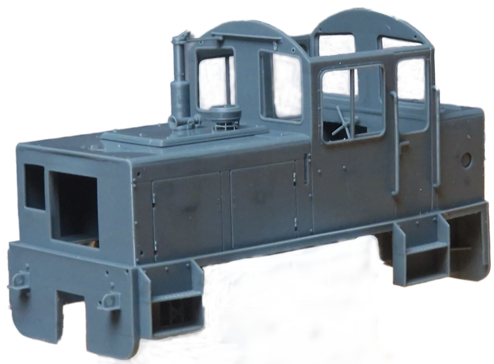
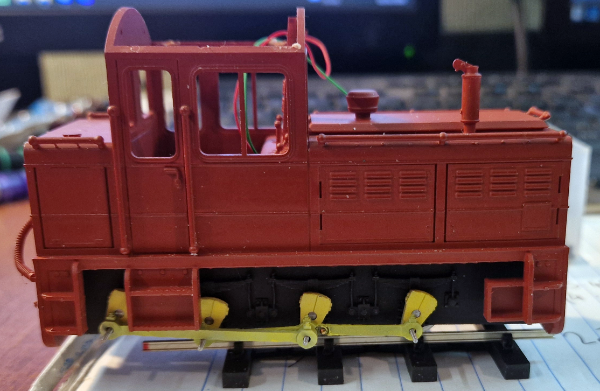
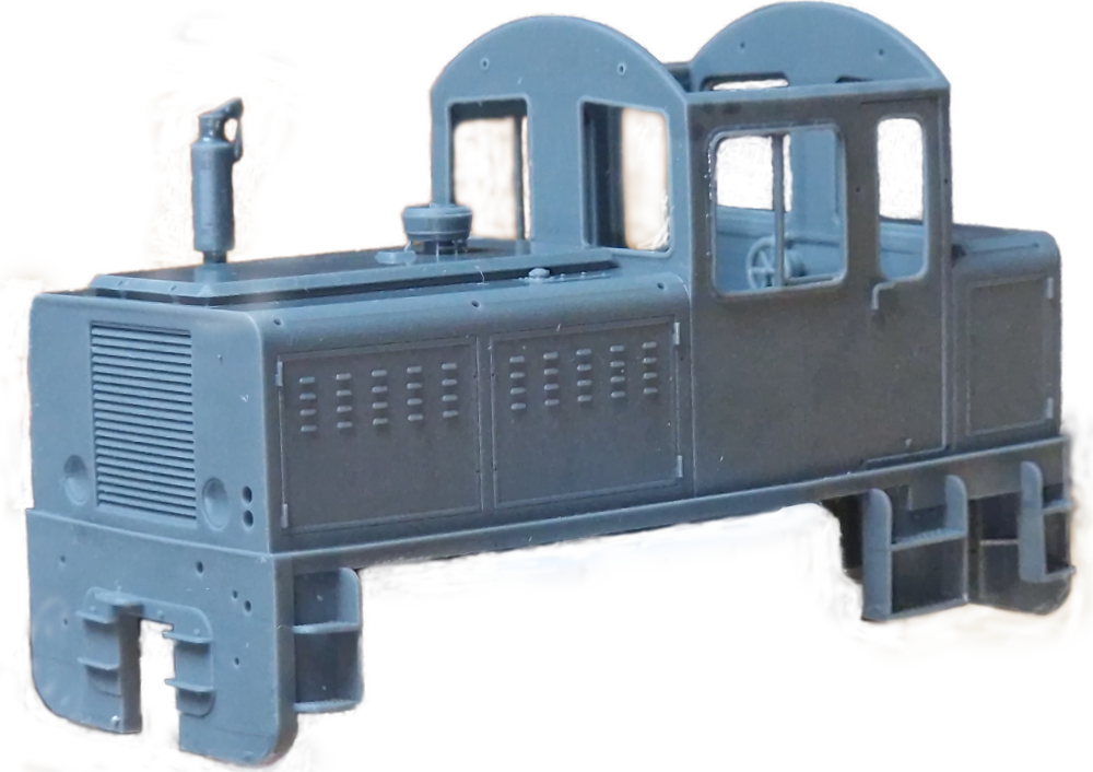
The revised Harlech Castle body now has many separate parts to add during the build. Handrails Grilles, glazing and lighting are all added later.
Criccieth Castle has a similarly upgraded with additional parts

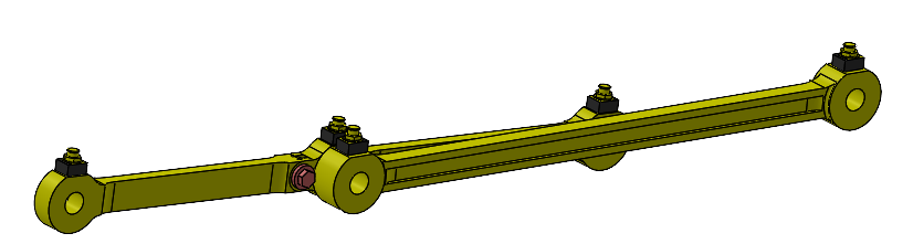
The shiny radiator trim is included in the rods etch.

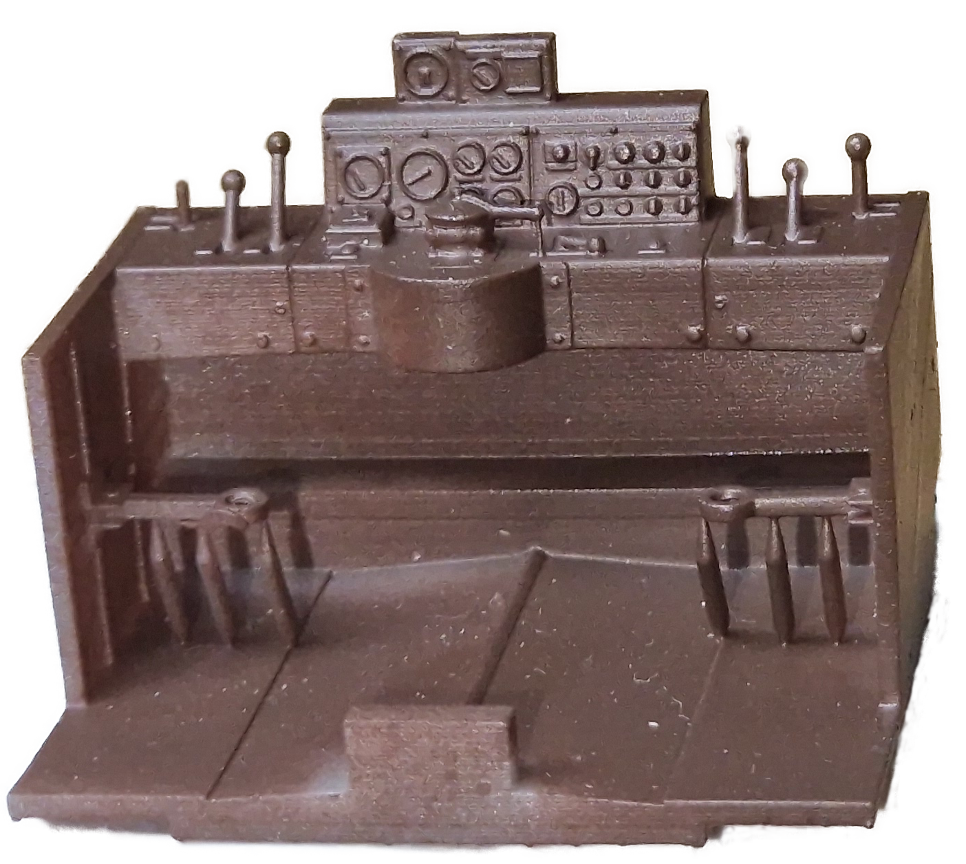
Individual drivers desks for the two models have been produced. This is the one for Harlech Castle.

FR staff who have seen commented that its inaccurate as the floor isn’t covered in enough junk

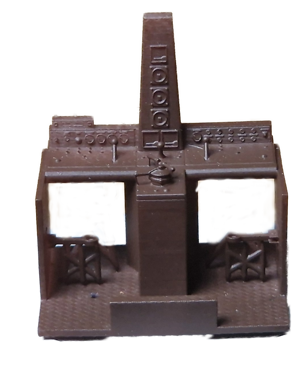
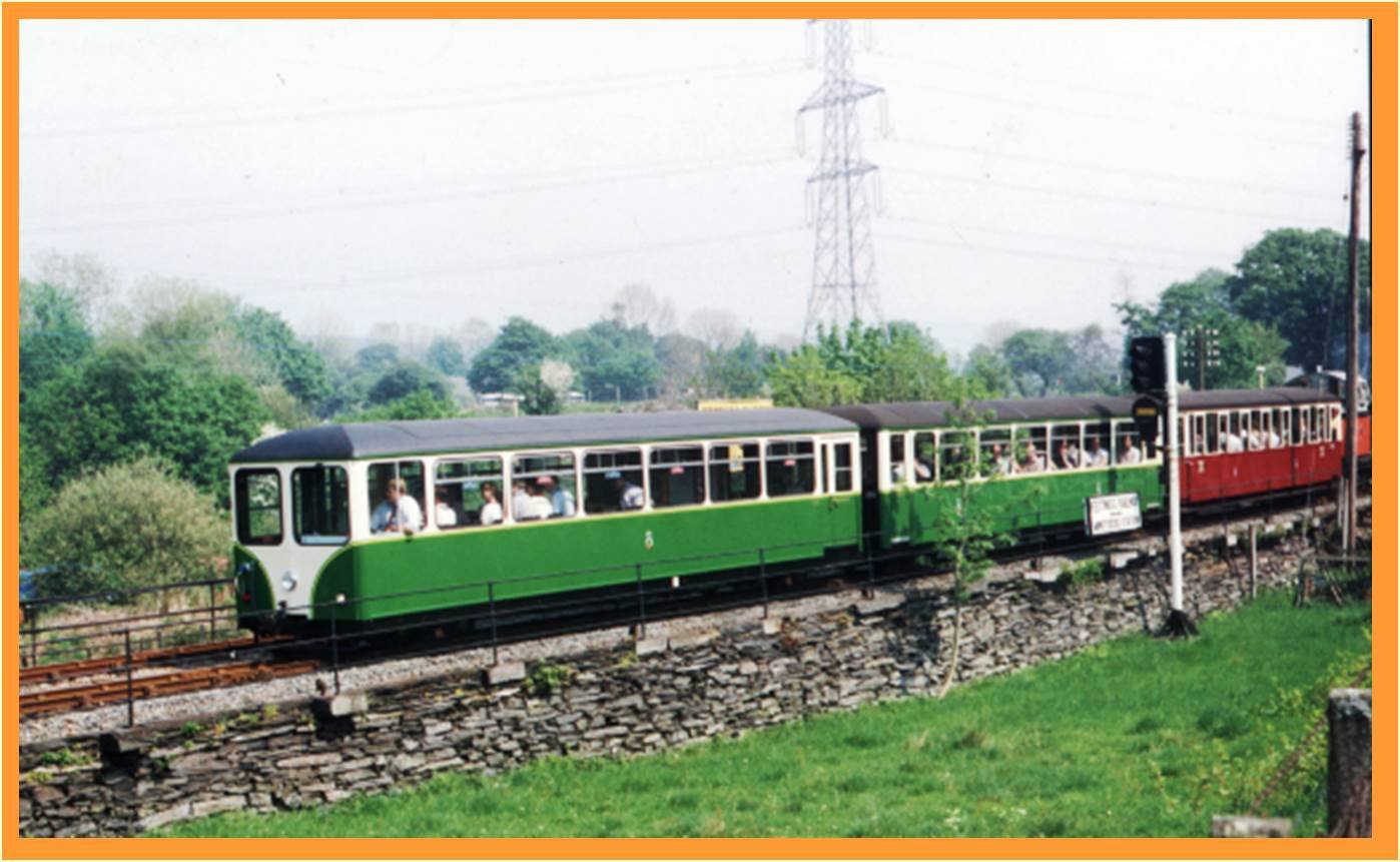
This is the desk for Criccieth Castle its different as it was built as a passenger diesel for use with the push pull train.

The as yet unproven plan is that these will mount on the chassis so they can be detailed and then put in the body.

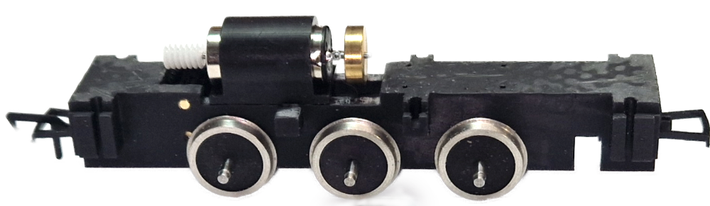
The chassis needs proving with the rods on and the springing added. It also needs the body mounts added to suit the new bodies
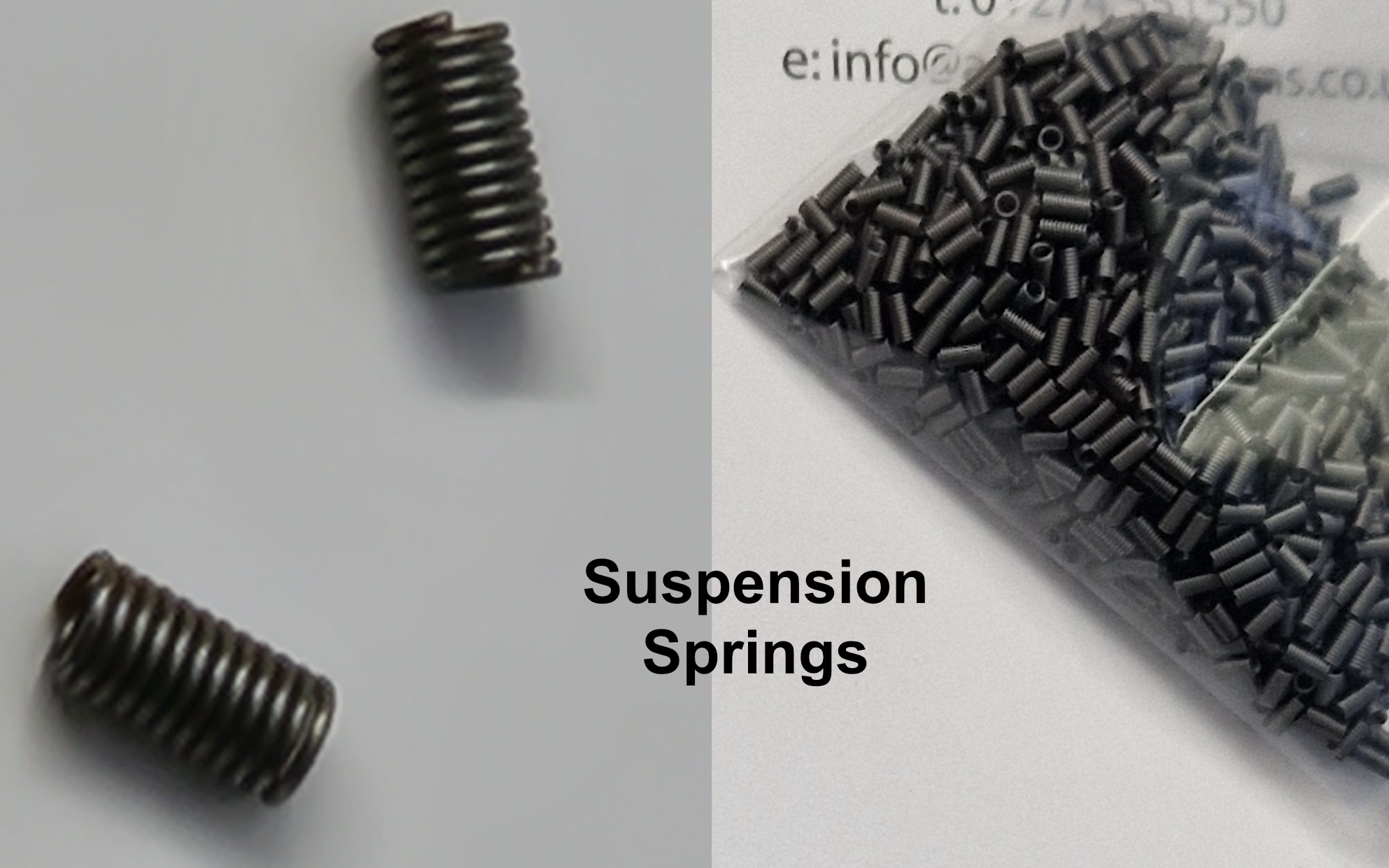
We’ve commissioned springs to suit the model and these have only just arrived
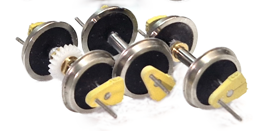
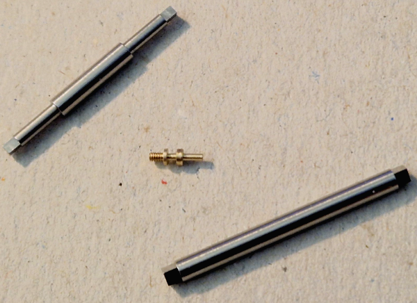
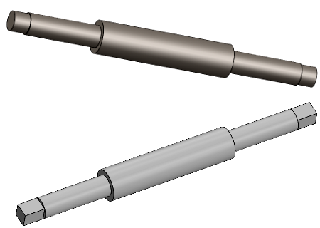
The axles and cranks are custom to these locos and now feature squared ends.
The aim is to supply made up wheelsets assembled and quartered ready to drop into the chassis with options for 14mm or 16.5mm gauge as required.
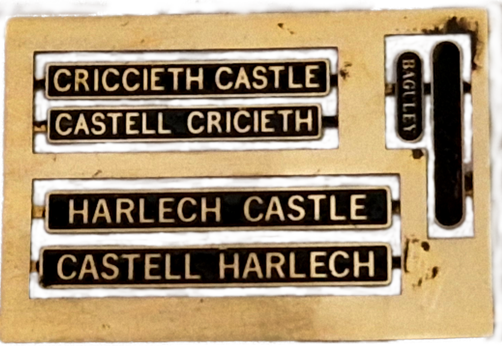
My original plan was to suggest builders got name and works plates from one of the usual suppliers. I then learned that they were just a generic typefaces.

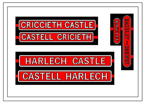
Instead we’ve done CAD based on the plates on the actual locos. The long blank plate has lettering too small etch so there will be a decal that sits on the plate.

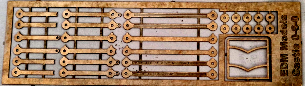
Etched rods have just arrived but haven’t yet been test built
Sound Project

Discussions are ongoing on recording the locos and creating a sound project on ZIMO N18 decoders.

Sadly, Criccieth is not co-operating and has just blown its engine up.


Follow links for the full story

coming soon

Loading

The BRYMSTON RR #28

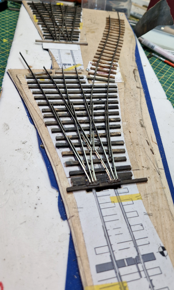
THE BRYMSTON RR #28 – TURNOUTS = part 3

After a hiatus caused by customers and a long birthday weekend away driving trains progress has been made with the stub turnouts. The next job was to make the moving rails and their operating arms/wires.  The plan is to operate them from underneath the baseboard.

To that end I wanted dropper wires from the underside of the rail to locate with a mechanism under the board. Criteria were: –

  • Silver soldered so it won’t come undone
  • Consistent placement so that the rails become a known standard to mate with the mechanism below the board.

That said I need a jig to me.

That opened a bit of a can of worms that included a mild rebuild of my bandsaw whilst equipping it with a metal cutting blade to cut the aluminium for the jig.

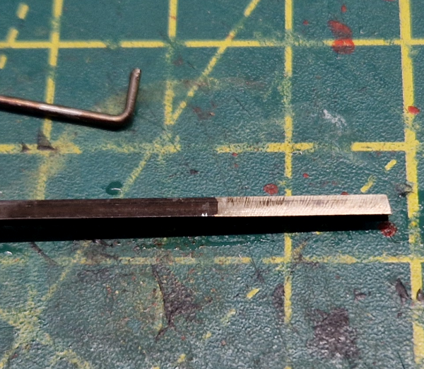
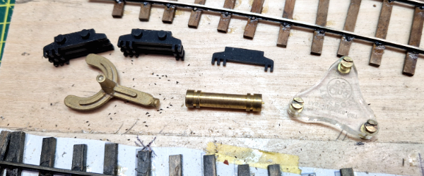
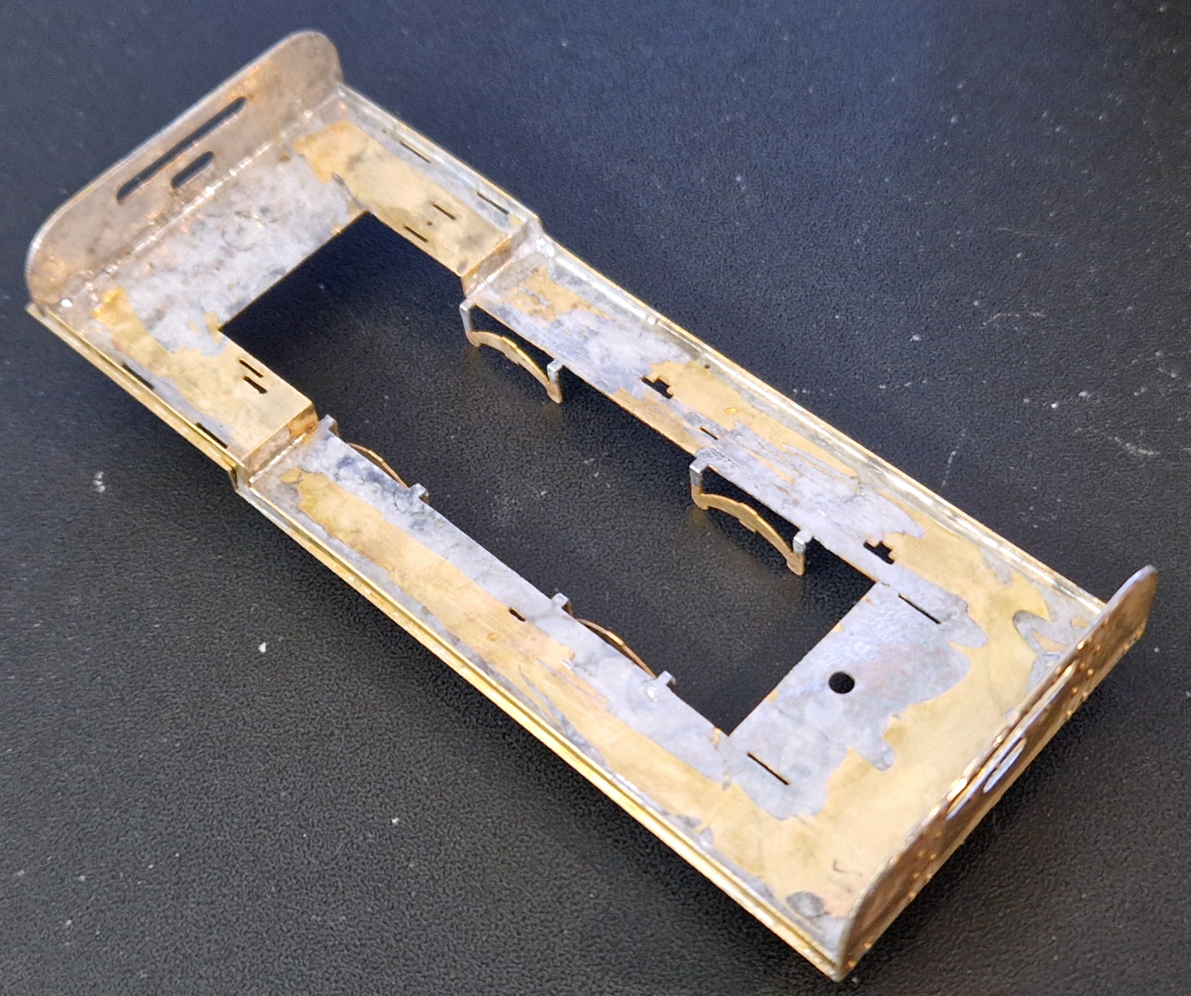
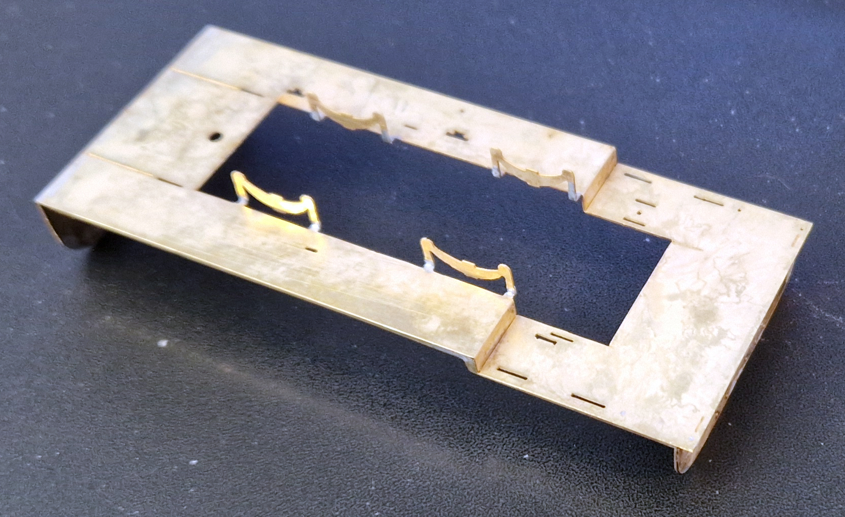
On the jig the aluminium block is screwed to the back plate. In this picture there are two bits of rail glued to the far face leaving a channel for the rail to be soldered locating it parallel to the back plate but spaced off it.

At the far right is an end stop, This has a Vee filed in it so not only does it set the distance it prevents the rail deflecting up or down.

The dropper wire holder consists of two bits of brass tube silver soldered to a bit of brass angle. Two bits of tube were used because I had them to hand but they resulted in a happy accident. One bit moved a smidgen such that there is a very slight misalignment. The happy result is the dropper wire is held tightly and stays where its put. A couple of layers of card spaced the dropper holder up to the centre line of the rail.

The droppers are 1mm diameter nickel silver wire. They are bent in a pair of pliers with the width of the blade acting as the depth gauge for the length of the bent bit.

Once bent they are held in a pin vice and were touched on a powered sanding disk to create a small flat on the bottom to increase the surface contact of the soldered joint.

The rail being used is Micro Engineering code 83 and its the weathered variety so the bottom face has to be cleaned of the weathering compound. Once clean both the rails and the droppers were left to soak in pickling acid for awhile –  precise time being one cup of tea and two biscuits. This gives them a final clean prior to soldering.

What is silver soldering? Its a harder and higher temperature method of joining two metals. Whereas your soft soldering with an iron uses a temperatures in the 150 to 350’C range this is in the 600-900’c range. Its advantages for modelers is that it can be the first part of an assembly and subsequent soft soldering won’t make it come undone. In this case its that its a stronger bond and unlikely to fail in a location where fixing it would be a right pain in the nether regions.

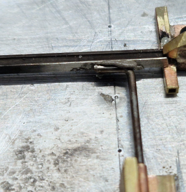
With the parts cleaned  they’re place in the jig and aligned.

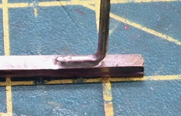
A smear of EasyFlow silver solder paste was spread on the rail before the wire was pushed into place and then a bit more was added with the blade of a scalpel. The solder paste is a combination of silver solder and paste flux. Mine is in a syringe and you can squirt it directly on to the work but as it takes some squeezing out I prefer to do so on to a surface and then pick it up and place it with a bit of wire or a blade.

At this point you could heat this to red hot with a small blowtorch and the solder would flow but following from an earlier experience doing the crossing vees I decided, after I did the first with fire, to see if my resistance soldering rig would do it.

Resistance soldering is done by passing a current through a joint that has either solder paste in it or the parts have been tinned. (coated with a layer of solder). It is more usually used for soft soldering where you place the parts in a ground plane (tin foil) connected to the unit with a crocodile clipped lead. The parts are assembled and held in the right place with a carbon probe connected to the live side of the unit. When all is in the right place a foot pedal is pressed and current flows through the joint melting the solder. Once its flowed the pedal is released to stop the current whilst the probe hold it all together until the joint cools and solidifies,

To do the higher temperature silver soldering I use two carbon probes so the current passes directly through the join. An early mod was to add a bit of business card as an insulator when I couldn’t figure why the transformer was buzzing until i realised the bodies of the two probes were touching the aluminium backing plate.

The video shows the actual soldering as it happens and you see the solder flash into the joint as soon as the correct temperature is reached.  I filmed this with my phone which was so close that I was placing the probes by watching them on the screen. Those who do keyhole stuff via cameras have just gone up in my estimation!

After allowing it to cool the soldered the joined thing gets taken off the jig and given another soak in pickling solution as this removes all the flux and soldering debris.

It just needs a light buff with an abrasive brush to clean it up ready for use.


I did wonder about some mods to the jig such as replacing the toolmakers clamp that holds the rail in place with a cam lock affair but instead I got on and just made enough closure rails to do all the turnouts on the layout and a few spares.

The next instalment will hopefully be about installing these and cosmetically finishing these turnouts


Coming soon

Loading

Castles in the Air

Quick update on shopping in China.

23/04/26 –  the shiny bits are in the air

Ahead of expectation the shiny parts are on their way


24/04/26 – Shiny Parts have arrived

Just after lunch the nice man from UPS arrived

Already the 3D printer is doing so cranks so we can do a test assembly.

Follow the links for the full story


Loading

THE BRYMSTON RR #27

THE BRYMSTON RR #27 – TURNOUTS – part 2

In the last episode we got as far as hiving made template in a photo package – I use Affinity. Now to prepare a base to build them on.

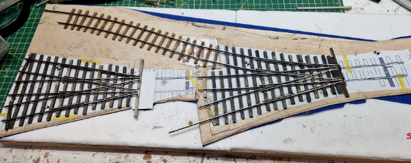
Firstly they were laid out on a sheet of 2mm ply to mark it and cut it to size. A thin, 0.4mm I think, layer of ply was added where the ties for the non moving parts of each turnout was added. This is done because the moving parts run on etched baseplates making them higher than on plain ties so the rest has to be lifted by that amount.

I then got a base of 10mm ply that would remain rigid whilst the turnouts were built. This was covered with a layer of 5mm foamboard so that any drillings that went though the turnout base went into something soft. The turnout bases were then fastened to the build board using a trick I saw in a guitar building You Tube channel. Both the underside of the turnout base and  the top of the foam board were covered in blue painters tape. One then had blobs of thick cyanoacrylate glue applied whilst the other was sprayed with accelerator. They’re then pressed together to hold them. The theory is that when you want them apart the tape just peels.  We’ll see as I’ve stuck spikes through it!

York Model Railway Exhibition was fast approaching and this was to be my show demo build so emphasis turned to making parts in prep that would be difficult at the show.

First up were crossing vees as I wanted these to be silver soldered to make them both rigid and impervious to later soft soldering activity.

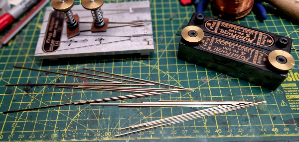
The jig is a Fast Tracks “Frog Helper” to which I have added the clamps. I think that the intent is that for soft soldering fingers hold it safely enough but as I was planning on pointing a blow torch at it and getting the rail red hot I thought clamps would be better than fingers.

I needed three #5’s and one #4 but I made several spares of each. They were filed using the Fats Tracks Pointform tool.

These come with Allen Screws as seen on the back one but I have done a mod to add thumbwheels as I can never find the Allen Key.

Next bright idea was these printed jigs hold all the bits for a point frog in the right place upside down whilst some wires were soldered across to hold it all together. There’s two, one for #5’s and one for #4’s

At the show three of us had a table on the top floor with a display of different scale narrow gauge modes and we were variously building track, wagons and coaches.

The show is a three day affair and is very convivial both at the show and at the after hours relaxing which may have been in a pub.

Turnout work commenced by making up the frogs and then laying them out over the plans. Ties were then added on to the plan adjusted to miss any of the wires holding the frog together.

There is now a bit of a gap in photo coverage as on day two at the show I had forgotten my phone (aka camera) whilst on day three I forgot.

The rough summery is that the frogs were laid on the plan and cut to make the combined or leading crossing. There is probably science that could be applied but it was mostly guessing and estimating. Once happy that vee was soft soldered and the entire unit glued down to the ties using track gauges. With that done other rails were added using the track gauges.

Show now over and back at home I was keen to crack on now with all the tools to hand and with my camera handy.

This is part of my collection of track gauges some bought and some 3D printed. The best “standard” is the Perspex one, this gets used where gauge is critical. The roller gauge is a bit naff as its too small in diameter and the grooves aren’t deep enough. Some of the printed ones also feature fixtures to hold check rails in place.

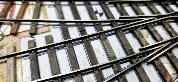
Eventually that got all the fixed rails in place. At this point they are only glued down. That said having wanted to move a rail I can say they are stuck in place and aren’t going anywhere.

They are glued with aliphatic glue applied by a pipette nozzle fitted to the bottle. This wicks in under the rail and as it starts to go off surplus can be removed with a wet paintbrush.

The rails are now fully spiked as well as glued.

They actually aren’t “spiked” as such as they are pushed into drilled holes and then glued by brushing the aliphatic glue on, leaving it for a couple of minutes whilst it wicks around the spike and down the hole then wiping/wicking any surplus off with a wet paintbrush.

Surplus glue leaves a shiny mark on the ties but a whizz over with a nylon brush in a rotary tool removes it. Final job for this chapter was to cut the rails for insulation gaps between each of the sections

The next instalment will cover making the moving parts, jigs to attach the operating wires and some cosmetics. I’m still thinking about the jigs design

 coming soon

Loading

THE BRYMSTON RR #26

THE BRYMSTON RR #26 – TURNOUTS

Firstly, its been ages since I added anything to The Brymston RR Saga. This is a true reflection of how much I have done in the last 18 months. I may have messed up and made a reckless commitment!  Immediately after this years Trent Valley Group Modelling Day in January some idiot [me] may have promised the organiser [also me] that The Brymston RR could appear at the January 2027 event.  First thoughts were that if me and me told no one then we might get away with not mentioning it again but the real screw up was that I did it in front of witnesses.

Now at the moment only the curved board has any track on it, and then only on the lower level. Its also the only board with the start of any scenery on it!

Better get on and lay some track then. Hold your horses. A reminder, this layout is 0n3 and there is virtually no ready to run track available so its all going to need to be hand built.

An added variation is that all the turnouts on the layout are going to be stub turnouts.

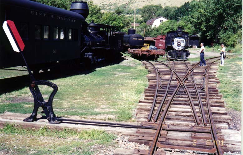
If you are not familiar with these then have a look at the picture of the three way stub. There are no blades. The approach rails are just moved to line up with the route you want to take. The advantage of them is that they cab be shorter than a standard turnout. Disadvantages are they are low speed, no positive locking of the rails and you’re actually bridging a gab crossing from the switch rails to the fixed rails. They were popular for their simplicity and whilst the main line moved away from them they remained common on industrial, and low budget railroads such as a logging and minerals concern like The Brymston RR.

THE TRACK PLAN

Might as well start with the difficult stuff! Entry on this board is straight into an assymetric three way stub. The line up to the higher level is a #5 angle whilst the one towards the front of the layout is a #4. This leads straight into a second three way but this is a symetric #5. The #4 route will limit what can go that way but that line will likely be the storage track with something like the cabeese parked on it. By taking the straight road through each you get to 2 road of the shed and it being a straight run through the turnouts anything that makes it round the curve will be able to make it to the shed,

THE CUNNING PLAN

As I type this the 2026 York Model Railway Show is two weeks away and I have a demo table there with two mates so I have decided its three days of point building for me. There are some things that need doing in advance for this and one is to make templates

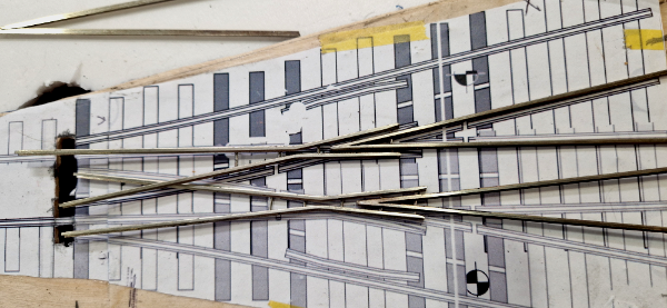
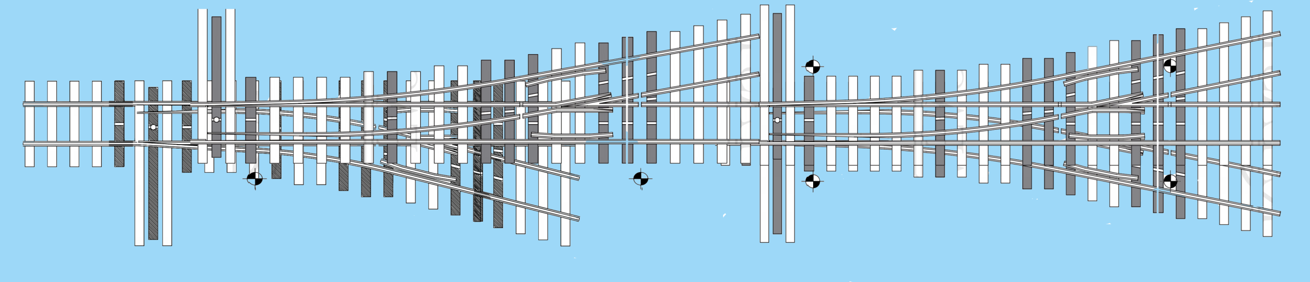
The first problem is that Fast Tracks free printable turnout templates don’t include three ways or stubs so some editing was attempted

When it looked like that would work some more effort was put into modifying the standard points with this result

After that the templates were laid on the layout to check they fit so a removable base could be made for them. That’s ongoing and I’ll report that in the next episode.

Loading

A man’s home is his castle


EDM MODELS ANNOUNCES CRICCIETH & HARLECH CASTLE KITS

Yes we did. In October 2025. We even said they’d be available early in 2026.

So where are they?

Background

This kit development started when a friend persuaded Fourdees to do a simple blow up of their 4mm model to 7mm and then persuaded the usual suspect [US] to build it for him whilst doing one for themselves.


The US then started on the internet with the usual “someone” and “somebody” should do a chassis for this. He’s very good at telling other people who to spend modelling time/ development time / money with bugger all commitment from himself.

Just so happens that that struck a cord with me. Time for an aside:

[Aside Start] I have an association with both prototypes. I am a driver on the Festiniog Railway and am qualified to drive both locos but more than that I am also the rolling stock electrical engineer and wired them both up. Harlech is of such an age now that I wired it when it was being built and have since renewed its wiring. Criccieth has been wired several times as the control system for the push pull train evolved. For these reasons I also wanted a model of them both. [Aside end]

This was all happening just before the 2025 Narrow Gauge NOW exhibition and I asked Fourdees if they could do me a body for each of them to collect at the show. They weren’t hopeful that there was enough time but Dani arrived at my stand with two still sticky bodies for me and I had an early draft of a chassis to show. At this point a plot was formulated to jointly produce 7mm scale kits for Harlech Castle (as now with the wide bonnet) and Criccieth Castle.

The deal was that they would produce amended versions of the 4mm bodies whilst I would produce a working chassis to suit that would work for 16.5 and 14mm gauges which I would sell as a complete kit for each loco.

PROGRESS

If I were to suggest a planning method for the quick release of a kit or, at least, maintaining an delivery schedule it would be to keep a pair of perfectionists away from the project.

Wheels

The correct diameter stainless steel tyres have been acquired and wheels made up.

Initial builds, as in the photo, used the axles I had made for the Quarry Hunslet regauging project. These have plain ends and need a quartering tool to assemble them.

Ideally the axles would be a smidge longer than the Hunslet ones.

Crankpins

Its fair to say I didn’t take the world shortage of crankpins following the demise of Markits into account.

I looked at using our alternative system which I’ll call the Alan Gibson method but a problem with that was it requires a hole in the rod bigger than the rod boss so the rods would have needed to be oversize.

The solution was to order our own design from China. More on that below.

Axles

The top axle in the photo was the one we had in stock and to use it I was going to have to step the cranks out by about 0.5mm.

This didn’t sit right with me and as mentioned we were exploring Chinese manufacture of parts right length and a square end seemed like a good idea

Jackshaft

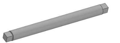
This needs to be longer than the axles as the connecting rod sits outside of the coupling rods. Plan A was some sort of split of a standard axle with the joining sleeve also serving to keep it central.

Plan B was to add it to the Chinese Manufacture list

Rods

Plan A was cast brass rods. The intent was to eliminate the need for soldering of etched parts. I got as far as having several sets cast but either the consistency of them with all the holes cast in or the work required to jig drill them too much.

Plan B is the kit will include etched rods. The CAD for that is just being completed. To maintain the “no solder” option assembled rods will be a paid optional extra

Nameplates

Plan A was to just refer builders to a well know etched plate supplier or for me to buy them in bulk to include in the kits.A discovery was that their plates were generic and not actual copies.

Plan B was to supply a set of etched plates, derived from the real things, in the kit

Tests revealed that the Baguley Drewry text is too small to etch so Plan C is an etched empty plate and a decal for the words. The artwork is off the etchers shortly

NG North – Project Review

Dani and I met at NG North to review the chassis and bodies together for the first time.

The result was a fairly radical shift from just amending the originally 4mm bodies for 7mm scale to completely reworking them, effectively new models for 7mm.

The 4mm bodies had a number of features that had to be printed oversize or overly thick as they needed to be at the minimum thickness required by the printer to reliably print. In a simple blow up to 7mm scale these same areas became bloated and overly thick. The 7mm bodies will be finer and will have a lot of parts supplied separately.

Hoping to have examples of the new bodies at the Porthmadog Model Event in 15/16th May


SHOPPING IN CHINA……

….is pretty bloody scary if you have never done it before. Essentially…

  • You arrange the order by sending a drawing to someone you have never met who is clearly using a false name because we couldn’t cope with the Chinese version.
  • Agree a price which in terms of my pocket is a lot of money.
  • You send that sum to a bank in Hong Kong.
  • You then hear nothing until you ask, “did you get the money?”
  • You then wait and hope that something shows up.

To be fair I was dealing with a firm that was recommended by others that have used them and Crystal (probably not her real name) couldn’t have been more helpful. The slight panic of having apparently sent a lot of money for it to appear to disappear was a function of a money transfer on a Friday and it not getting noticed. The response to my “did you get it” was a slightly panicked response with a grovelling apology and evidence it had been received.

Why go Chinese?

Cost simply. I have a UK supplier of CNC’d parts who I will continue to use for some items bit his price for the crankpins was beyond what I could afford and that had the potential to stall this project.


Having started a dialogue about the crankpins and the associated washer I added the square ended axle and jackshaft to the order and the price for all of it is less than the UK price for the crankpins alone.

These parts, in particular the crankpins, will have applications beyond this project. 

LATEST NEWS FROM CHINA – 21/04/26

Despite all the assurances and guidance from other its still a pretty nervous wait having sent just shy of £2K into the unknown. I was told to expect it to be 25 days for the parts to be ready which puts it sometime in May so I was delighted to receive an e-mail with some photos attached.

They are now made but are still in China.

I’ve been told to expect a tracking number in a couple of days and they are coming by air so they should take days rather than weeks by boat


WHAT’S NEXT

Once I have these parts I can get on and do the chassis mods to use them and get some running prototypes. Hopefully I’ll have something to show at the Porthmadog model event on the 15th & 16th of May but the beginning of May is pretty fully committed with Festiniog Railway nonsense as we are doing some things to raise money for Blanche’s overhaul.

MONEY, COST OF LIVING AND SO ON

This doesn’t get mentioned or considered by those who think “someone” or “somebody” should do something but all the stuff mentioned above is expense. Forgetting the time for now I have spent over two grand without a single order or payment for the models and with the etches it’ll be over three.

Meanwhile other work has to be done and completed to keep the money coming in to pay the bills so this project can’t have my full an undisturbed attention. It has to fit in with spare time.

I will open up sales for pre-orders soon but not until I am happy with a deliverable product, have a handle on the final costs and have a delivery window I am reasonably confident of.

Follow the links for the full story


Loading

Narrow Gauge North 2026

Yesterday was Narrow Gauge North in Pudsey and the short summary is that Annie and I had a great day.

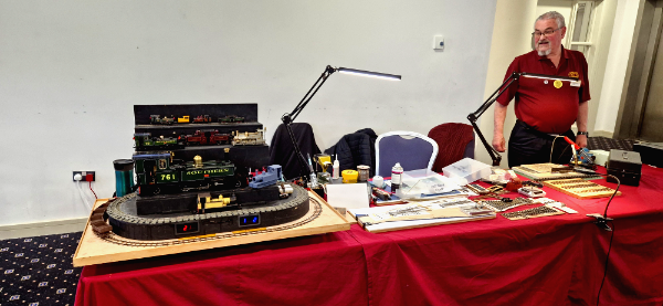
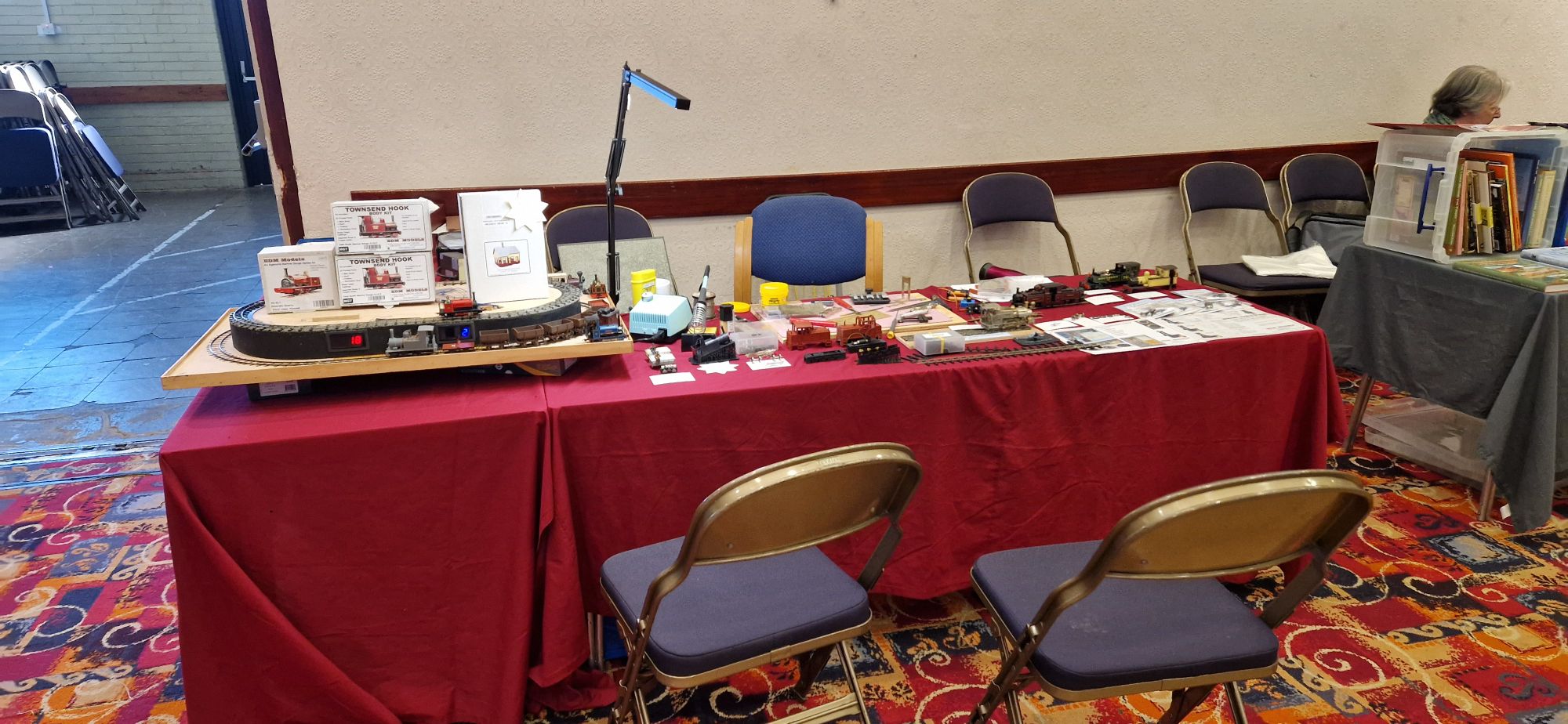
It’s a show that I always used to trade at with my EDM Models stand but this year I was just there as a demonstrator and in a different location to what was the “usual” spot. The only photo I have is this “just before it opened” shot.

I didn’t get that much done but then that’s not really what the day is about. Those two guest chairs were almost continuously occupied with people discussing what I was doing, having a go at soldering or just generally having a catch up. As the time the 16,5mm gauge Townsend Hook was going round and round on the lower level of the track whilst 14mm gauge Alice went round the top.

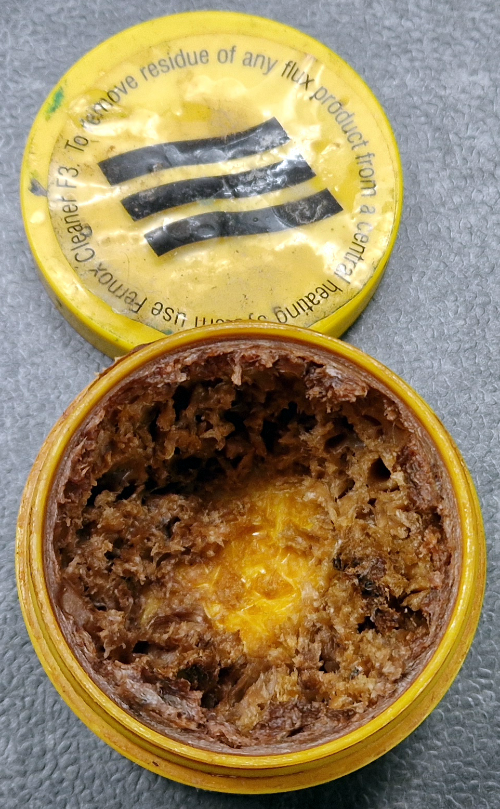
There was one major revelation though. I swear by PowerFlow flux for my kit soldering but when you leave the lid of the pot it changes to a brown gungy paste. Still works and absolute treat but it doesn’t look great and it can take a bit of spreading.

Users will recognise this  gungy mess!

This stuff is used for plumbing so it has a party trick for that application that can be a pain for modellers. Once its been heated it starts a conversion from acidic active flux to a rock hard inert crust where the soldering happened to stop it eating your pipes.

However, if done within an hour or so sticking under a hot running tap and it runs off like butter off a knife. Add a bit of amateur science and a scrub with CIF which is alkali and its all clean. I give mine a swim in the ultrasonic cleaner.

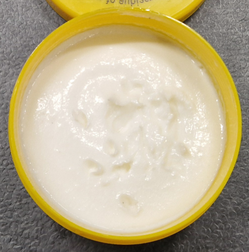
Regular users may have a distant memory of when a pot looked like this, smooth, creamy and easy to apply. A Friday night dash to Screwfix was the result of my admitting that the old pot was finally too gungy.

Did I actually make anything? Well yes! As if I didn’t have enough projects on the go I have set about Project Lillian as I have decided to call it. There will be a lot more about Project Lillian in future posts but it has started with my building the running plate and buffer beams from my ex Agenoria Kit SL5 for the Penrhyn Quarry Port Class.

There were three of this flavour of Quarry Hunslet, Gwynedd (316), Lillian (317) & Winifred (364) and they are all still with us. More on Project Lillian and the Castle Diesels another time


Loading

The problem with doing locos for others…

The problem with doing locos for others is that I put my heart and soul into it and then have to deal with the pains of having to give it back…

Here is a case in point! Its a good job its 0n30 and my Brymston RR is 0n3 or it would be even harder.

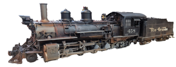
This is one of those jobs that’s gone on and on for far too long. It arrived here as an undecorated anonymous K27 with just the standard DC wiring in it.  It did arrive with a very bent tender drawbar as well as a selection of the lights not working.

Things It’s had done to it: –

  • New LED Lighting with a resistance board hidden in the smokebox.
  • Custom made back lit 458 number boards.
  • Soundtraxx Tsunami, keep alive and speaker all in the boiler.
  • Motor Gearbox stripped cleaned and regreased.
  • Brake gear amended to stop it shorting.
  • Drawbar repaired.
  • Fall Plate modified.
  • Decaled as #458 and Flying Grande road name
  • Coaled over a foam lump.
  • Paint and Weathering with acrylics by airbrush and pigments by brush
  • Sealed with a waft of Dullcote

Continue reading

Loading

Folly #2

Folly #2  – These are in no particular order

OK, I admit it I like Claytons.

I probably shouldn’t as they were pretty rubbish, unreliable and short lived. With a 450 HP engine in each end at 900hp they were woefully underpowered. They spent a lot of time running around in pairs to get the power up and, probably, give you a chance of getting home.

They were a product of the BR Modernisation plan built from 1962 to 1965 for a job that was disappearing as fast as they made them. 117 were built, 87 by Clayton and the rest subcontracted to Beyer Peacock. They couldn’t even standardise them between batches as each had different multi-working gear! Their biggest achilleas heal was the engines. In most of them they had six cylinder Paxman engines.

Looking back with bucket loads of hindsight Paxman engines were crap in rail applications, but they weren’t alone in that. I think the load profile, flat out or idling was something diesel engine manufacturers hadn’t encountered before. Two were built with Rolls Royce engines as an alternative but they were rubbish, just in a different way, and ended up with Paxman engines.

By the time these were ordered the English Electric Class 20 was already in service and a reliable success. As these were a single cab at one end design they spend most of their life in pairs with the cabs at the outer end. There are still a good few of them running today!

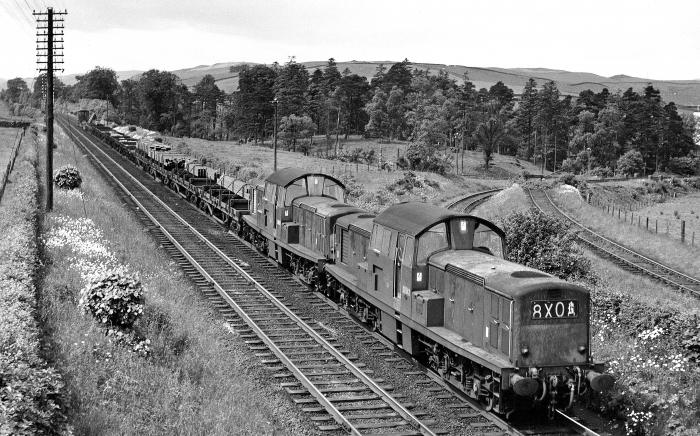
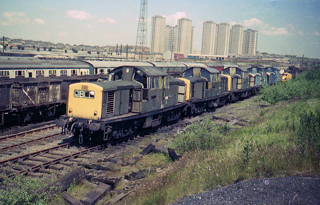
British Rail came up with the spec for what became the Clayton as they figured they needed to address the poor visibility of the Class 20 but they were so unreliable that all but four were lined up in yards like this as  prelude to scrapping.

On a mid 70’s Merry Maker trip from Derby to Edinburgh we bunked round Miller Hill Yards to the east of Edinburgh and there were lines of 17’s along with 24’s & some 25’s all lined up waiting their fate.


I mentioned four escaped. Three made it to the Railway Technical Centre in Derby which as a Deby spotter is where I saw them. Most of the time they were inactive but one was used on the Mickleover Test Track which I used to cycle past regularly. Even then they were wrestling with poor adhesion and one of them used its gen set at one end to move whilst the other generated Plasma to torch the gunge on the railhead. I believe from some info from a colleague in later life that it also torched signalling insulated block joints.

The fourth, D8568, after withdrawal in 1971, went on to see industrial use at Hemelite, Hemel Hempstead and at Ribblesdale Cement, Clitheroe, and was then secured for preservation. This is the only one still with us.

So to MY FOLLY. The Models

I’ve a thing for models of things I saw when I was a kid in Derby or that I worked on. The research centres three qualify under the “seen as a kid” banner [as does the APT-E that sits on my test track shelf).

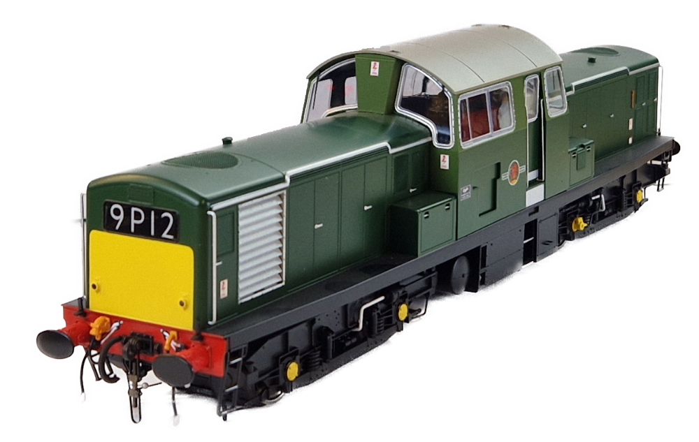
I thought I had satisfied that itch with the pair of Heljan 00 models seen in the pictures. They’ve had an occasional run on the test track but spend most of their time posing on the collection shelves.

When Heljan announced the O gauge version I said NO! Whilst I have a collection of 0 gauge tank engines this would be too big.  I remained unanimous in my decision for some six years. Then I got offered one part chop in a no cash changed hands deal and it was too good an opportunity to pass up. Even then its sat under the bench in its box for weeks and have now only appeared because I was doing a load of other photos.

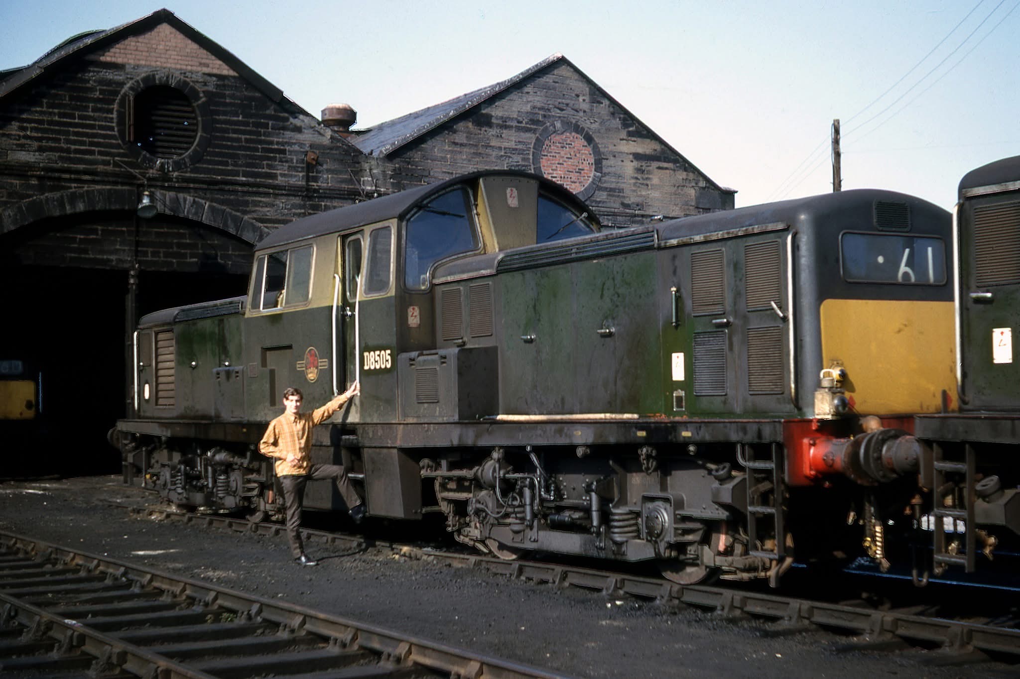
What is its future. Well it’ll get DCC & Sound installed and, whilst its in bits it’ll get a driver in the cab. Then its for a serious weathering. Not massively filthy but work worn as in the picture below. When? Who knows!


Class 17 D8505 BR green livery Motherwell June 1967 (S)

Addendum of daft ideas

Now imagine some of the body shells had survived to now -unlikely I know but play along.

In one bonnet, using a modern diesel and alternator set, you might even get 1500 HP in there given the things they stick under the floor of modern trains are just shy of a 1000. Do that to both ends you’ve got a 3000HP diesel but more likely stuff the other end with batteries and you’ve got a fancy modern hybrid that looks the business.  New AC traction motors and all of todays fancy electronics and you got a modern loco that works and looks the part.

Loading

FRED

F.R.E.D.

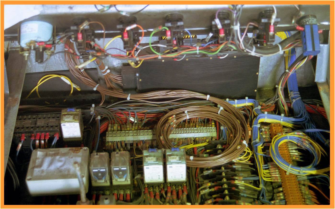
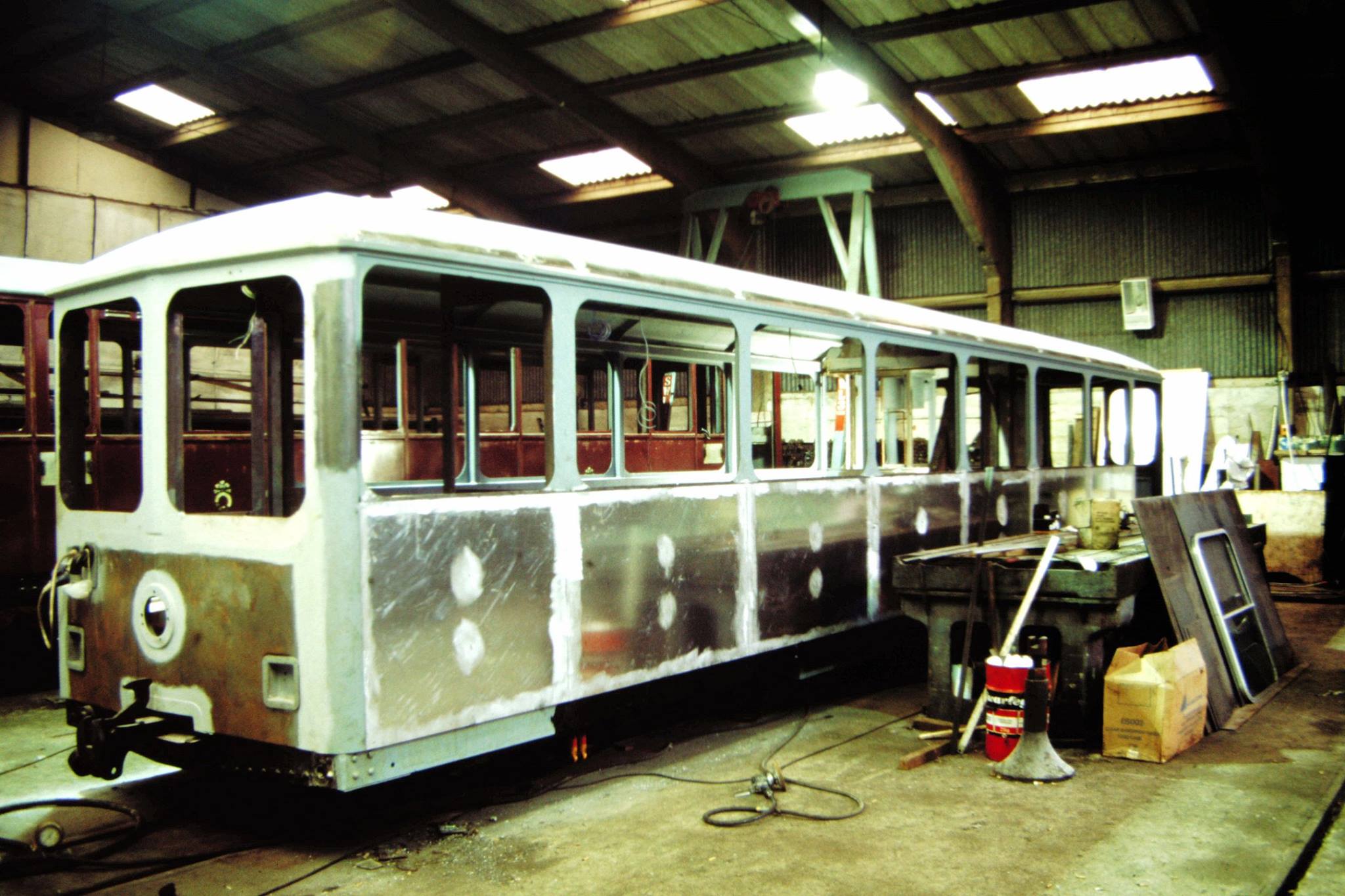
What on earth is FRED? FRED, was and is once again the Festiniog Rolling stock Electrical Department.  FRED existed in the 80’s & 90’s and then sort of fizzled out. It was a group of volunteers that developed in my time on the full time staff doing projects like rewiring carriages with what it still referred to as “the new carriage electrical scheme” (blue plug scheme) and the push pull train.

It kind of fizzled out as the gang developed other interests and family life got in the way. There would be the occasional burst of activity like wiring the diesel Bill or rewiring Upnor Castle but for some time now since Ged Perks retired the routine stuff has been done by contractors.

Now were putting the band back together!

You can’t help but notice that last year with the fire risk we asked a lot of our diesel fleet and are likely to have to do so again. Asking a lot without some plan for TLC is asking for trouble. This has been recognised by management and a few of the old gang have been approached to do some of that TLC to the electrical side of the job. Initial approaches were to individuals but it quickly became apparent that we needed to reinvent some sort of cohesive group, hence the rebirth of FRED.

Apart from the need for a new name to include the Welsh Highland the group needs to recruit some more volunteers, get a tool kit together and sort out our workshop. That is a plus, as part of the Great Boston Lodge Rebuild we have a nice warm workshop, although at the moment it has more the look of a slightly tidied skip.

Initially, at least, we’ll be taking on specific projects. Whilst this will represent a major cost saving over using contractors the main reason is that railway vehicles have specific needs to both comply with the operational needs and safety requirements. This is an experience that we developed and have retained. I am reluctant to list the projects in the queue because when I do it seems to get longer as someone adds a CYJ to the end of it. As I type the list is: Sort Diesel #9’s battery charging, restore Criccieth Castles Deadman’s (these two are in hand), rewire Vale of Ffestiniog, rewire Moel Hebog, design and fit a Deadman’s to Harlech Castle.

Its very early days as we only got “volunteered” after this years bygones so I’ll report more in future magazines but for now I’d be delighted to hear from: –

  • Anyone who would like to help – don’t have to be a sparky, we can teach
  • A benevolent electrical wholesaler specialising in industrial equipment
  • A benevolent electrical wholesaler who’d lets us do a trolley dash through the tool section

I can be contacted on pmartin@ffwhr.com

Loading