This is another story about laser cutting but I have dressed it up as a modelling post with a recycling slant to make it about the birth of a new layout.

Henmore Dale as at York Model Railway Show 2013
We, the Trent Valley Group of the 7mm Narrow Gauge Association , used to exhibit a large 0-16.mm layout of the Henmore Dale Light Railway. It was last exhibited at York Exhibition, Easter 2013. It was a large layout that needed many hands and a large van to go anywhere and it couldn’t be set up in anyone’s home.
At the end of that exhibition some of the layout was damaged and created a rethink. That rethink had several false starts and then stopped with the untimely demise of one of our group, Tim Allsopp, in 2018. Nothing happened for ages but the group has now re-invented itself with a new layout in build.
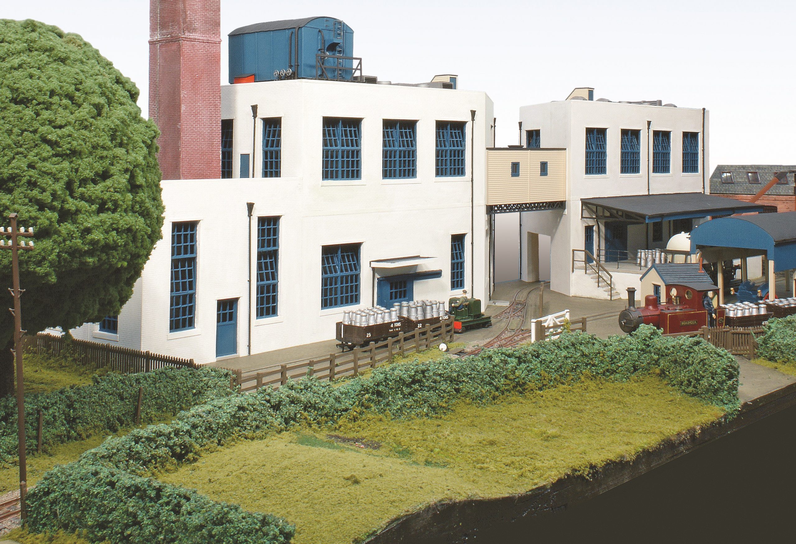
The Creamery
Quite a bit of the old layout headed for the skip but some bits were saved. The subject of this article is The Creamery.
It was the last bit without a home and was heading for sale or the skip when last January TVG member Phil, now a resident of Porthmadog, stepped in to save it.
His initial plan was to incorporate it in a layout he was building around four sides of his modelling room, basically four straight scenes connected by new corner boards. Having offered it up it was going to cause a problem in that it forced the adjacent corner board to have a ridiculously tight curve which would have compromised the whole layout.
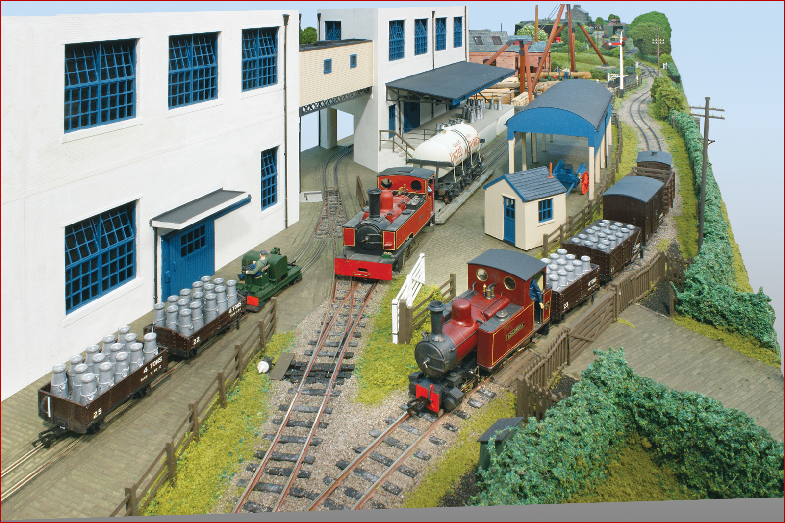
The main line to the right. Ends by the signal
Several evenings musing whilst sampling Phil’s rum collection (Phil provides my lodgings when I go to drive trains) came up with a wizard wheeze. Phil already has two roughly 8ft x 2ft layouts he takes to shows, one standard gauge and one narrow gauge. Our rum fuelled plan turned The Creamery into a third by the addition of a fiddle yard to one end and terminating the through line in a weed encrusted buffer stop. That way the main line becomes a shunting line whilst, in the future, the weed covered main line could be restored to run to another fiddle yard if 8ft got boring.
The new fiddle yard is added to the foreground of this picture. The rum consultations revealed that Phil was thinking a bit 2D for the fiddle yard, probably informed by his woodworking skills. I thought we could do better in 3D.
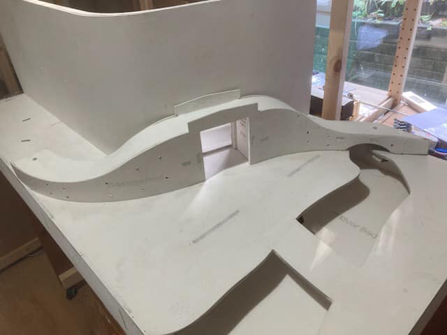
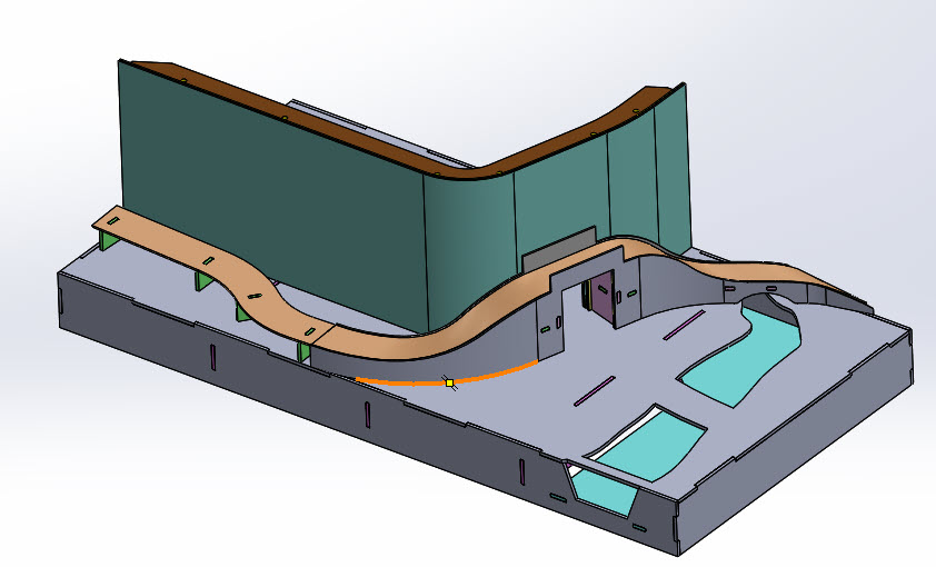 I set to with CAD and came up with this. All to be laser cut plywood with the main boards out of 6mm and the bridge and backscene laminated layers of 3mm.
The road bridge provides the scenic break through the backscene to a cassette based fiddle yard. The railway has to cross the river first. The below datum river and the above datum roadway and bridge force the scenery to be 3D. I admit I have a dislike for flat boards.
 Phil with basic artistic skills added some scenic suggestions thus. With that settled I had to crack on with the CAD and then get it laser cut and built up. The CAD generated the image above but from that 3D image it had to be converted to 2D flat files laid out for laser cutting.

I use Grainge and Hodder for my laser cutting and, with guidance, now send them files that are ready for the laser to minimise the additional work they have to do. As well as this project I did CAD for three others to be cut at the same time, a total of six sheets in all. We did hit one snag in that two projects had parts in that were too big for the courier. Turns out Allen of G&H and I were to be in Porthmadog a week apart so the long bits were dropped at Phil’s and the parts the courier would take were shipped to York.
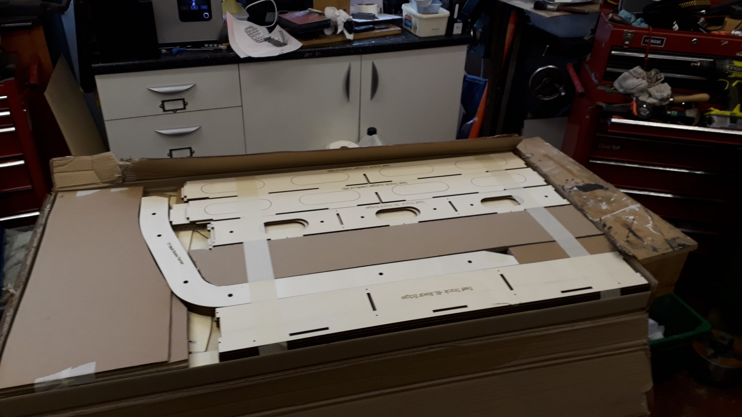 What turns up is a lot of cardboard and masking tape surround ones laser cut plywood. The tape is particularly evil as its the same colour as the wood. When you think you have peeled it all off there is always another bit somewhere.
I’d heartily recommend Grainge and Hodder if you want laser cut baseboards. (except the tape guy). They have a standard range of boards but will do custom works to your design.
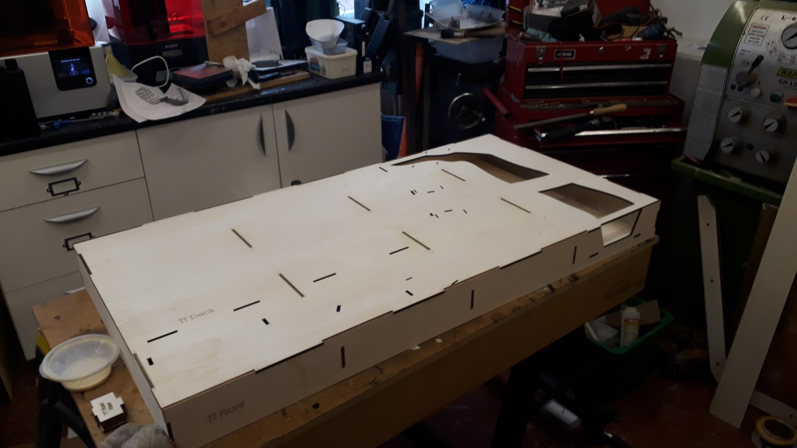 Well with the wood here and a delivery deadline enforced by a trip to Wales for another reason it was time to crack on.
The basic box of the board went together very quickly and once the glued had fully dried the braces at each end of the river section were cut away leaving just the railway bridge. That might come out when the scenic rail bridge is built.
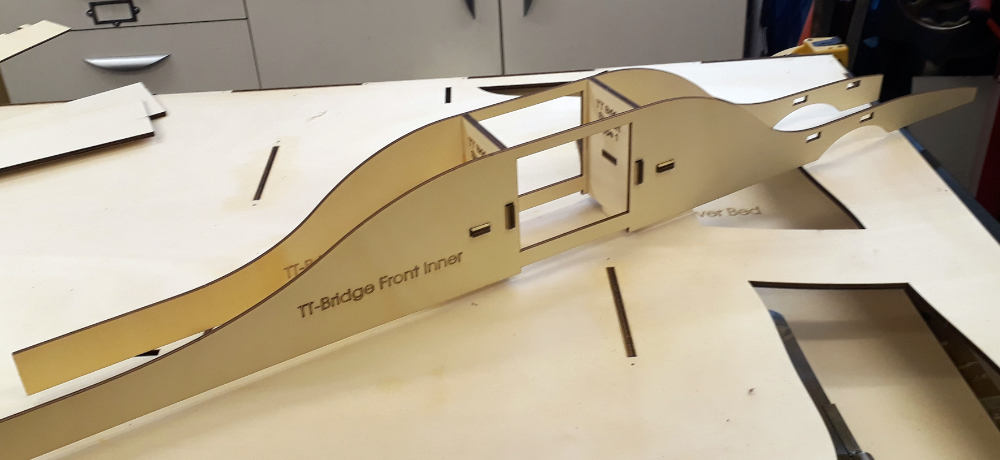 That was the easy bit. Now it was on to the first bendy bit, the road bridge. The only straight and parallel part of this is the rail over road bridge itself. The formers are 6mm ply and these were glued up with the inner layers of 3mm ply that will eventually laminated to the curved shape of the road way
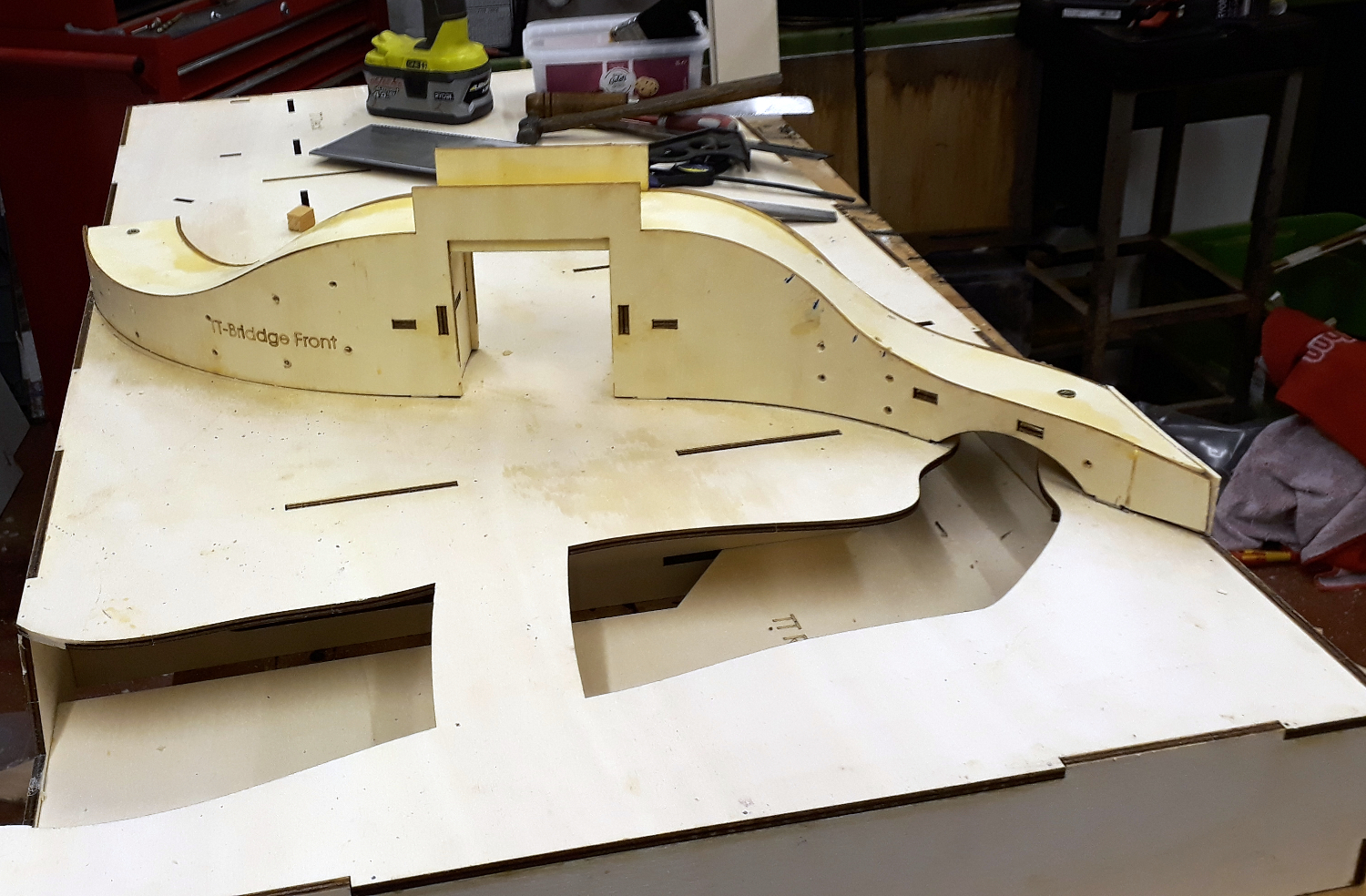 Next the outer 3mm layers were glued to the inners just on the parallel section by the bridge with cling film inserted to stop glue going beyond the flat bit. When that had set the bridge was curved to shape in a dry using the tabs on the bridge and the slots in the board to pull it to shape and the deck tried in place. With curves in every direction is soon became obvious a few mods were needed. The outers were drilled clearance for some self tapping screws whilst the inners got pilot holes. This was to pull the layers together when the glue was applied.
 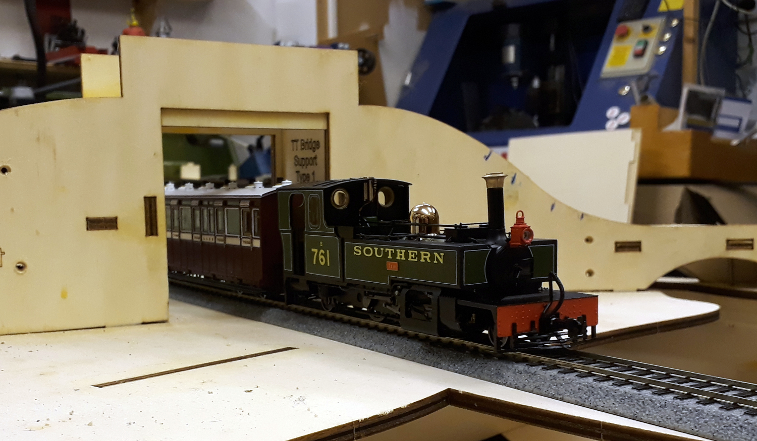 The inner faces of the inners got a number of blocks glued on to screw the deck to and to pull it in to shape. After a couple of dry runs the flat of the baseboard got a coat of Vaseline to stop glue bonding to it and all the surfaces to be bonded were given a generous coating of PVA wood glue chosen for its longer open time. It then became a race against time to get it all slotted into place, screws inserted, deck bent and pulled into shape and then lots of clamps added. It was then, or course, essential to pose a train under the bridge.
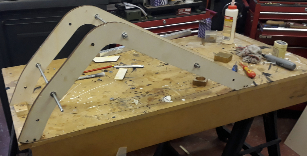 Forming the curved bridge was, at times, like wrestling a snake as it tried to spring back to shape but this was just a warm up for the curved backscene. This was to be curved and rigid enough to stand up on its own.
Unusual thinking ahead had included parts for a former in the laser cutting which was then assembled on my bench. It was actually screwed to the bench which proved to be a bit of a problem later.
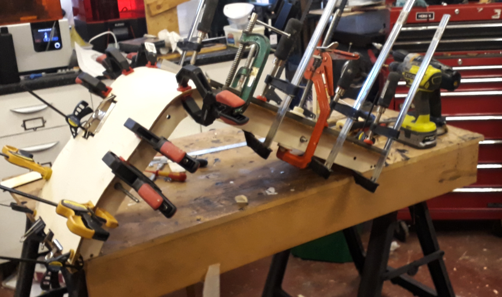 On to this former the inner layer of 3mm ply was pulled clamped and pinned into place. A liberal coat of glue was applied and the outer layer bullied into place. I think it was Norm on the New Yankee Workshop TV series that said, ” you can’t have too many clamps”. He’s not wrong. I even rounded up some of my smaller clamps from the model room and pressed a box of bulldog clips into service.
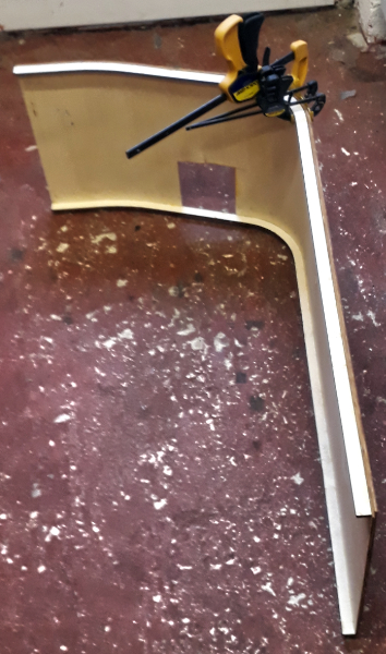 When the layers had set the top and bottom ribs were glued and clamped into place. It was at this point the problem with the jig was spotted. Having screwed it to the bench I had now covered the screws holding it down with the ply sheets. Brute force won here. The first layer had been pinned to the former with veneer pins which have a small head to with a bit of force the pins either pulled through the ply or pulled out of the former, Something must have gone right as it didn’t spring back to flat once released.
This, like the bridge, locate onto the baseboard with tabs and slots but at this stage I also added thickening blocks and added screws to hold them in place.
The final glued parts were done on the day of delivery to Wales so the little bit of backscene that needed some additional gluing kept the clamps on up to the moment it was loaded into the car.
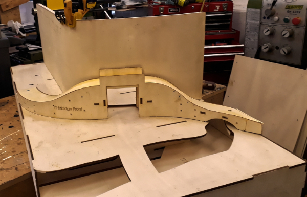
Delivery to Wales was just the end of the first chapter.
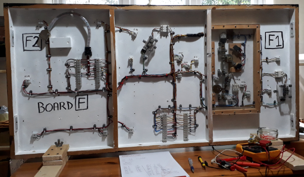 The existing board being part of a larger layout was comprehensively wired up so that it could be run from the main layout controller of switched to a local control to shunt the yard and includes things such as power operated gates. It was wired up by Tim and doubtless he did detailed wiring diagrams but we haven’t found them yet. Luckily all the wires had ID labels on them and we were able to trace where they all went and what they all did with the exception of three wires.
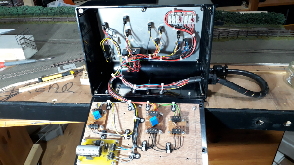 Turns out these were a provision for sidings on and adjacent board we don’t have.
The result of our deliberations is that we have worked out where to connect 12vDC from a controller and 16vAC for accessories needing a four core lead making up two connect the control box for the other NG layout to this one, A bridge rectifier added to the underside of the board will convert the 16V AC to DC for the gate,
 Making up that lead and its plugs and sockets is my homework. Phil has continued to work on the boards with all the wood having had a coat of primer.
This is done to prevent any damp there might be affecting the wood.
The resin casting parts bin has been scoured to find bits for the scenery and a facia for the road bridge has been selected.
One part of the spec was that with the track on a slight ballast shoulder so it can meet the fiddle yard cassettes a standard gauge milk tanker on a narrow gauge transporter wagon had to fit under the bridge. BIG SIGH OF RELIEF!


Very detailed work here makes my efforts look really amateurish! However it’s great to feel inspired to work towards greater advances, so thanks Paul.
Practice is part of it Iain. Keep going,