INSTALLING THE EDM MODELS REPLACEMENT CORELESS MOTOR IN A BACHMANN 0N30 SHAY
Faced with a Bachmann 0n30 shay that the motor had failed on and finding the Bachmann UK had not spares at all and that Bachmann USA only sold a complete motor gearbox unit some lateral thinking was needed. I could have ordered a new unit from the US but as I am based in the UK the cost of the shipping was more than the cost of the parts but I also have these coreless motors in stock for other projects. The result was a kit to re-motor the Shay with a high performance 12v DC coreless motor using a 3D printed adaptor.
Bit of an Oops
A very small number (about 4) of these kits have escaped with the wrong length sleeve used in their assembly. As a quick check the distance from the motor to the outer end of the gear should be around 12mm. On the escapees the the distance is around 15mm. With the wrong length shaft the gear will miss the gear its supposed to mesh with and foul on the bottom of the gear case.
Theoretically, the fix is push the worm up the sleeve 3mm and cut the excess off but there are some potential pitfalls as rthe worm is very tight on the sleeve so I suggest you contact me for guidance.

SOME THINGS TO NOTE
These are the instructions for the kit so are here in the instructions section but there is an entire discussion page here https://ngtrains.com/blog/bachmann-0n30-shay/
The loco in the following pictures is a bit of a basket case that it slowly being rebuilt to be an 0n3 model with a wagon top boiler but it illustrates all we need to see here without taking a complete model apart
The motor shown in the following photos is a double shaft model. The ones supplied in the kit has a cut down shaft as its about 3mm too long
You can buy the kit on my website www.ngtrains.com at the time of writing the exact location is here. If that doesn’t find it look in the motor section or search “motor upgrade”
Step 1 – remove the Ashpan Casting
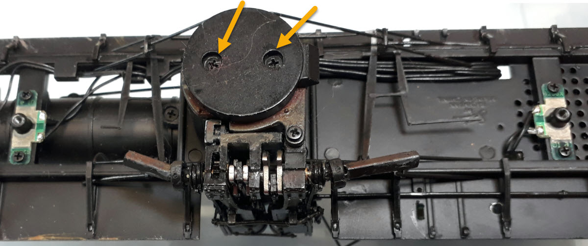
Remove the two arrowed screws and take the ashpan casting off. Note – the `beak’ faces to the rear when it goes back on. Also if your line has a hump in it and your shay catches on it this will be the bit that catches – leave it off
Step 2 – Prepare to remove the Drive Unit
The base of the boiler unit and the cylinder unit come out of the loco as one.
 |
|
Step 3
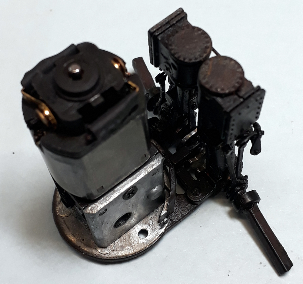
The base of the boiler unit and the cylinders should now pull down away from the body. Once its so far out you can access the wires on the motor and either cut them close to the motor or unsolder them.
What you have in your hands now should look like this.
Unfortunately we have to take it further apart to access the motor fixing screws.
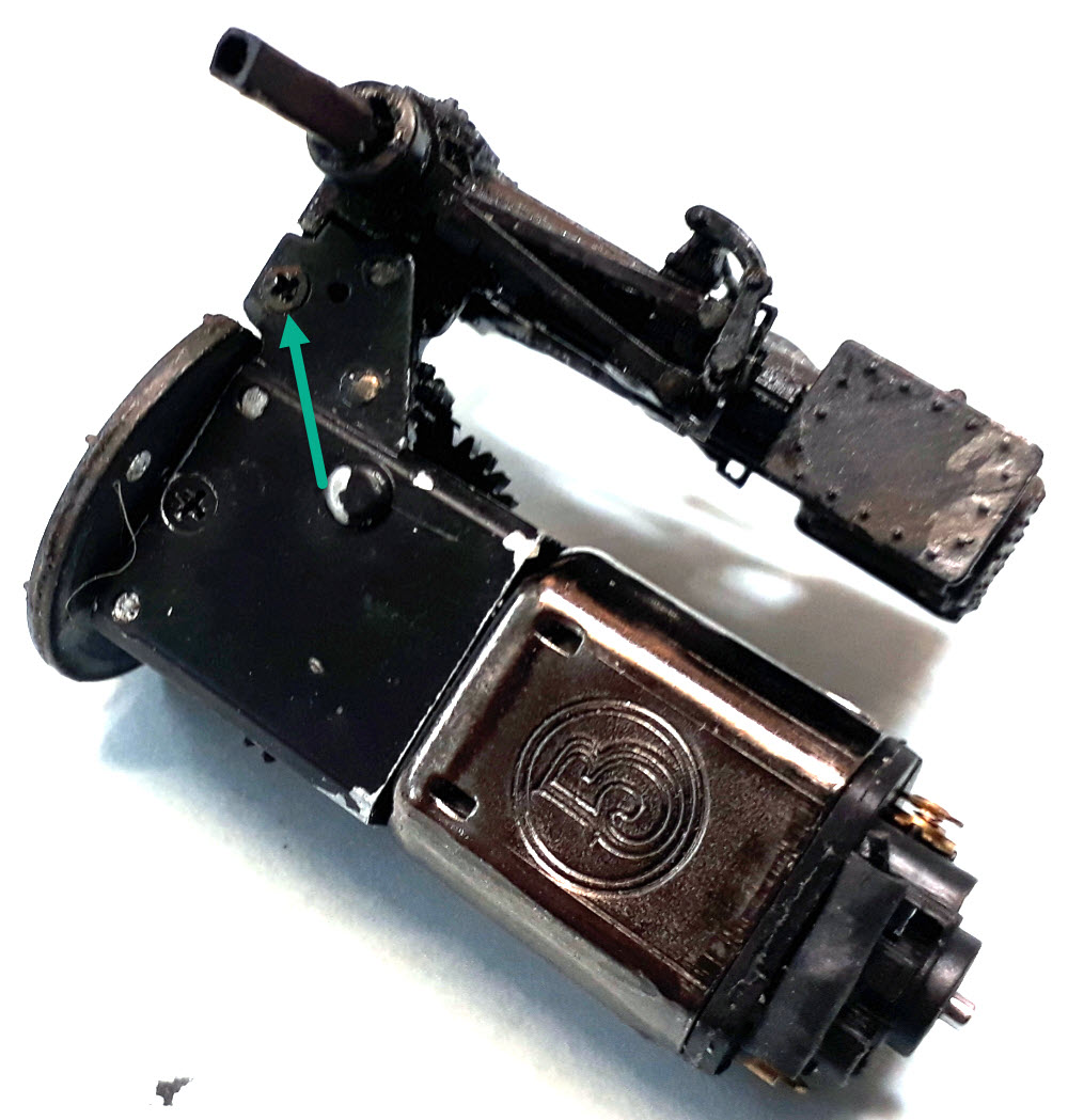 |
Step 4Take the screw marked with the green arrow out. Note this one is smaller than all the others. Also now take out the two screws that had red crosses on them in step 2. |
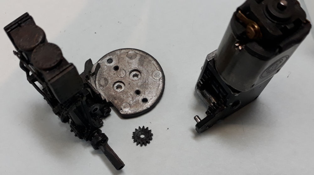 |
Step 5With a bit of jiggling as the gear mesh binds a bit as you take it apart you get this. Catch the gear as it come off the spigot because its very good at running away and hiding (that’s one of those `guess how I know’ moments |
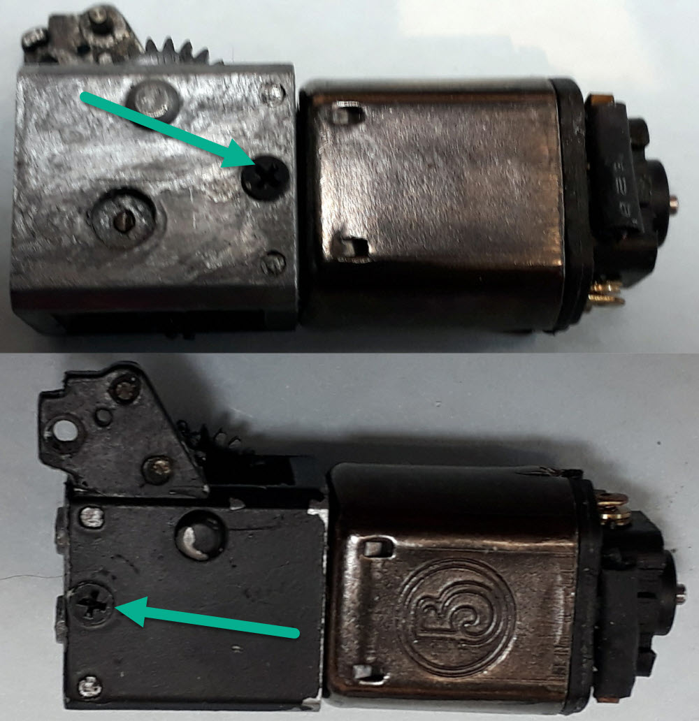 |
Step 6Now you can remove one the one screw each side of the gear housing. At this point the gearbox can come apart but it should stay together on the spigots in the casting. |
At this point I suggest you have a tidy up and make sure your work surface can catch any parts that fall out.
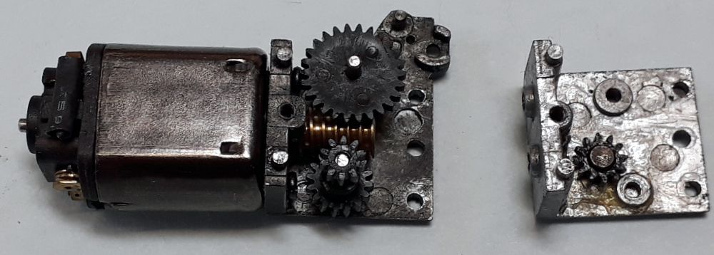 |
Step 7Lift the shinier of the cast parts away from the other. Try to leave the gears in place as you do. |
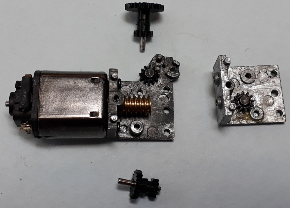 |
Step 8Lift out the two spindles and the gears on them. Try to keep them together and note how the gears on each shaft interlock with each. |
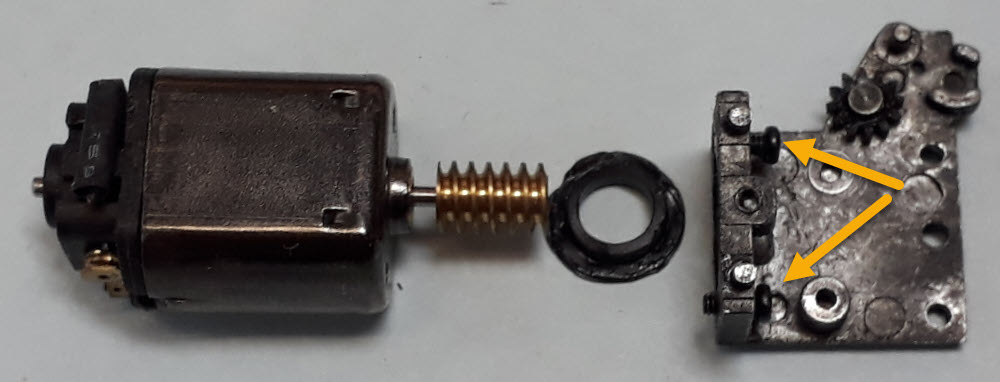 |
Step 9Undo the two screws arrowed that hold the motor and withdraw the motor and the plastic bush . |
Two things now before we go on
- Firstly, the plastic ring isn’t required in the rebuild and,
- Secondly, if your motor is fried and its both convenient and easy for you to do send it to me. I can reclaim the worm gear and use it as a pack more kits
 |
Step 10The new motor fits in the 3D printed sleeve which replicates the function of the original plastic ring to keep it all concentric. |
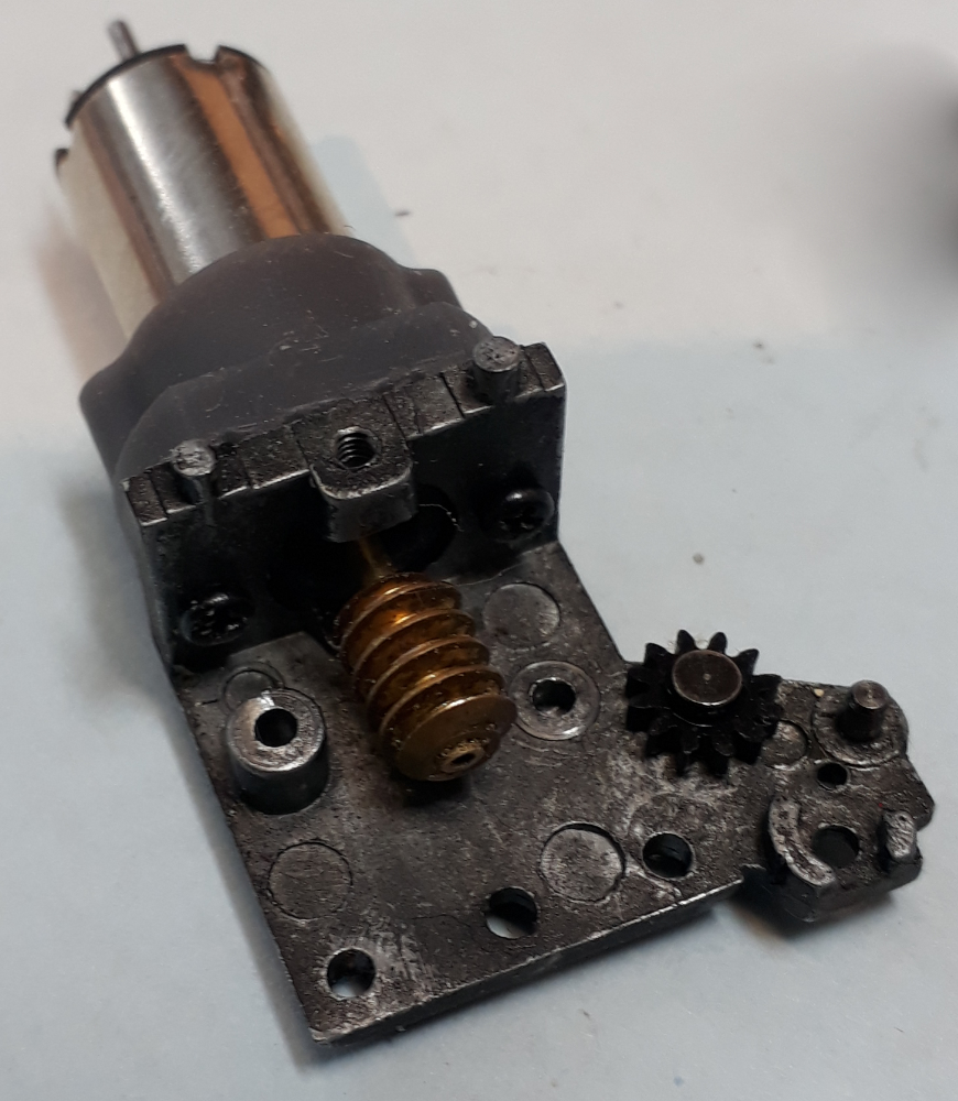 |
Step 11The new motor screws into place using the original motor mounting screws Update: Seems the original screws are only just long enough so to ensure more engagement from 02/06/22 all re-motor kits will include some longer screws. Use these instead. |
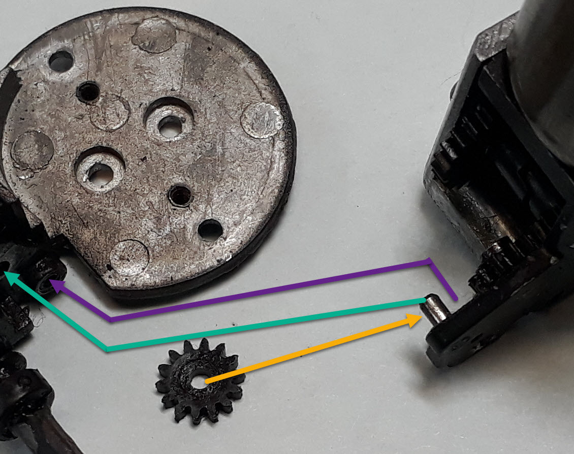 |
The Tricky BitThis needs a bit of dexterity, patience and, probably, you need to pull the face you pull when concentrating! The gear goes on the shiny pin The shiny pin then goes in the hole in the cylinder casting The screw (the small one) goes through the motor mount into the hole shown At the same time you need to feed the gear into mesh with the one in the cylinders which may mean turning the crankshaft a little |
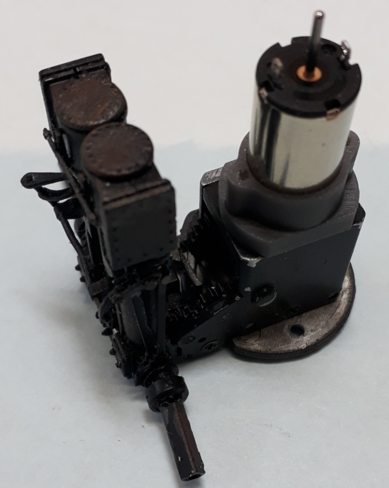 |
Step 12Sorry to do this to you but now its the “assembly is the reverse of disassembly” line. Tips
|
THINGS TO NOTE
- When you connect the wires to the new motor feed some power to the pick up to see which way it it runs if the drive goes backwards with the controller in forwards swap the wires over.
- If the loco you have fitted this motor to is DCC powered you may need to revisit the motor settings to optimise them for Coreless motors. With the latest ZIMO, ESU & TCS decoders their auto tune feature will sort this for you.
