Murder of a Garratt In this introduction to `Murder of a Garratt’ the first joke has to be “well, I wouldn’t have started from here”
Episode 1 is a bit long so you may want to get a brew!
The target of this build is a Garratt that is 138(ish) in lined red and the starting point is a Backwoods Miniatures 0-16.5 Chinese assembled ready to run Garratt in Black. Its been a project a long time in the making consisting of about three years plucking up the courage followed, so far, by three or for days of wanton destruction as I set about £2K’s worth of loco with a cutting discs, files and sanders.
The Backwoods Miniatures kit and the ready to run loco were the best NGG16 kit on the market – by way of being the only NGG16 kit on the market! In truth its a bit, well, wrong. The kit part of it (not talking accuracy here) is poor. Its origins are a kit designed for 009 from artwork drawn to 8mm/ft scale, twice full size. To work as a kit in 009 their have to be compromises on the level of detail that can be reproduced. This is all fine but it is still a challenging kit to build and get running well. Have a search for the Bron Hebog blog to see examples where a cracking result has been achieved.
Then came the bright idea to use that same artwork to produce the 7mm/ft scale kit. First problem is the scale of the artwork. When doing hand drawn artwork (now obsolete) the idea of drawing to a large scale and then photo reducing it to the etch size is to hide/mask, call it what you will, errors and fluctuations in the drawing – there is not copy and paste function on a pencil! 8mm down to 4mm is less than is typical, 8mm down to 7mm is frankly, bloody useless. The result is bends that don’t work, fits that don’t work and details that look twee when 009 compromises are blown up to 7mm scale.
The next item is the model accuracy. The real NGG16’s were built in, I think, five batches each with differences to the previous batch. The first three were built in Belgium – see #87 on the F&WHR. They have the new running gear that prompted the new class designation but had riveted tanks and bunkers like the previous class. They also had the short cab (no window to the left of the door). Later batches had different shaped tanks of welded construction (so smooth) and the cab with the rear window. They also had different water fillers in the form of a trough rather than a round hole. [Stopping #87 in the right place for water with just the round hole can be a challenge). The model has the later cab and tanks the later welded shape but they’re covered in rivets! This is just a few of the detail differences, I could go on but I won’t.
The donor loco is one from a batch of kits that went to China and were assembled by San Cheng and then sold as complete ready to run loco’s. These differ from the kits in that some parts of the kit that didn’t suit mass assembly or were too fiddly were replaced by Chinese made parts. I got one of these loco’s. It sat on a shelf in my eye line in my model room and over time the compromises and inaccuracies got to me so I sold it and then got asked to sort it out.
The target is something that looks like 138 in its lined red livery at sometime in its F&WHR history. So, smooth tanks, different water filler, different lubricators, new headlights all with DCC & sound. It will be getting the round Stones headlights as, in my opinion, the current automotive ones fitted, whilst effective look crap. That makes it 138-ish rather than accurately 138. The joke about the bloke going to Curl Up & Dye barbers and asking for his hair cut like David Beckhams and getting a short back and sides. That’s not like David Beckhams he protested. It would be if he came here was the reply!
Now I have plucked up the courage to start and have passed the point of no return I keep coming back to “well, I wouldn’t have started from here”. Follow on to see if I can salvage this one.

LETS TALK TANKS
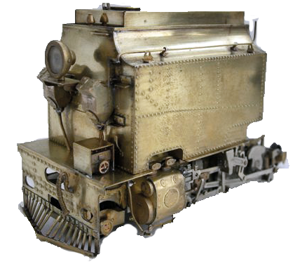
See all those rivets?
Shouldn’t be there!
The later batches of NGG16’s had their tanks and bunker platework welded and not riveted from new. The F&WHR engines have also had replacements made that are also welded. There was a change of shape from the riveted ones to the welded ones and the kit for some reason has the welded shape but is covered in rivets. 
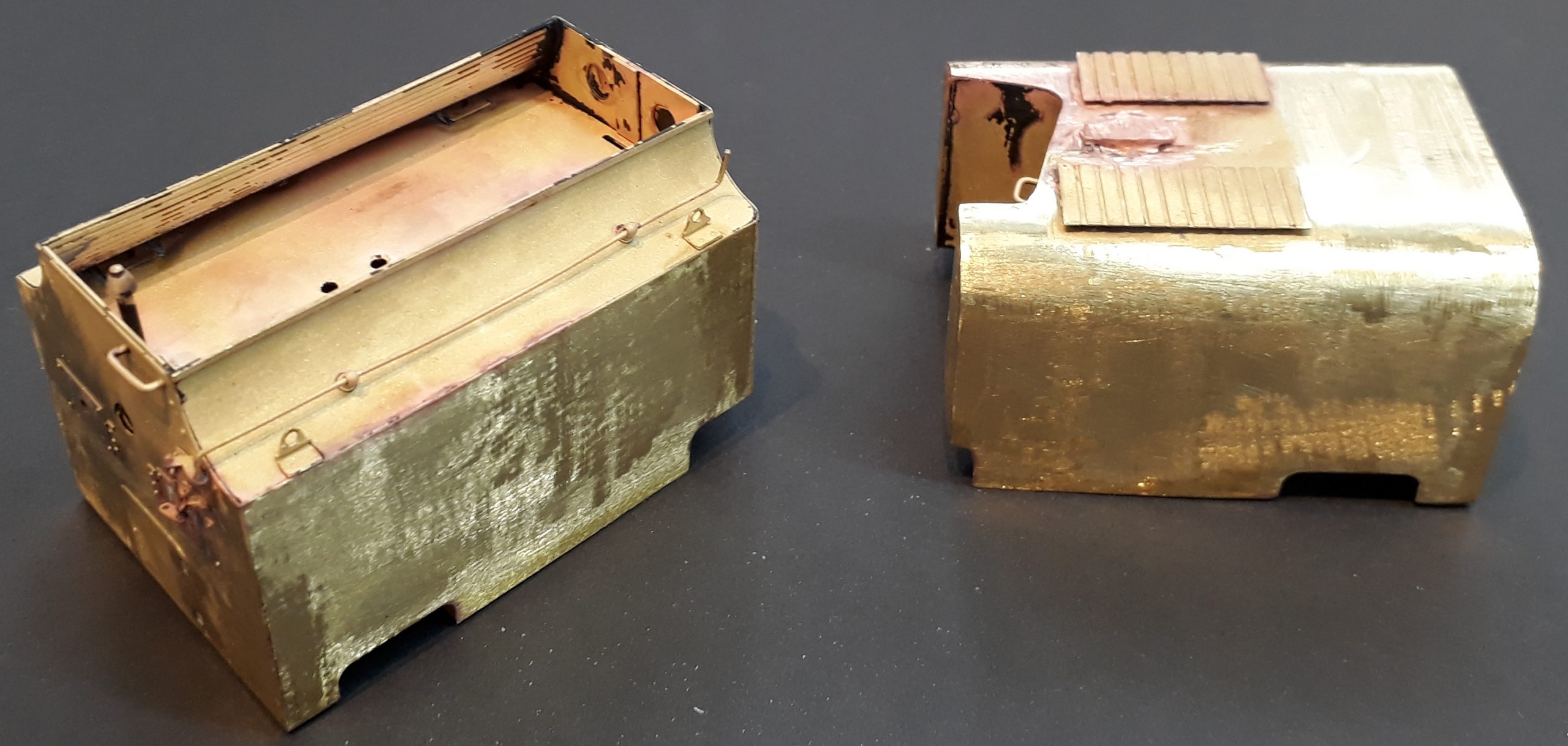 Only one thing for it then! Blowtorch, files and sanding discs to the fore.
First, the tanks were treated to a trip through my mini sandblaster and then a swim in cellulose thinners to get as much paint off as possible. Then nearly all the raised detail on the ends was un-soldered to give as smooth a surface as possible. Why will be revealed later.
The sanders, light brackets and lights and the hinges for the cupboard door were removed. Then it was files and sanding discs to remove all the raised rivet detail. The walkway boards are about to go.
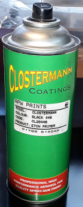
Once sanded as much as the eye can see on bright metal they all went for two swims in my ultrasonic cleaner, first with added cleaning solution then a plain water rinse. After that they were handled only with gloves on and moved into my drying cabinet. [That sounds grand – its an old metal electrical enclosure with a light bulb to add the heat]. After an overnight in there I put the can of etch primer in to warm up for ten minutes before shaking the living daylight out of it.
 For painting brass kits I use an etch primer and usually in a rattle can. I was put on to this stuff, Clostermann Etch Primer, by a build thread on RMweb and its now all I use. Me being me though I have it in three colours, and it rattle can and ordinary form. Providing the surfaces are clean it sticks like the proverbial to a blanket and on things like under-frames doesn’t need a top coat.
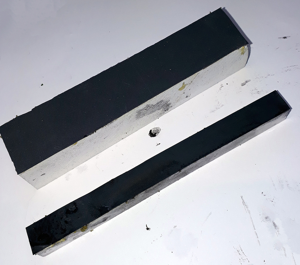 With one coat of primer on I could see how well I had done with getting the surfaces smooth and, where I hadn’t, do something about it. What I was needing to do was get the surfaces flat so some preparation was required. To get flat surfaces you need flat abrasives so some wet and dry was glued to some plastic blocks I had. I used 1000 & 6000 grit wet and dry.
The plastic are some off cuts of a architectural modelling material but some bits of wood will do. It was stuck with Evo Stick which last as long as the abrasive does and can then be peeled off and new wet and dry added.
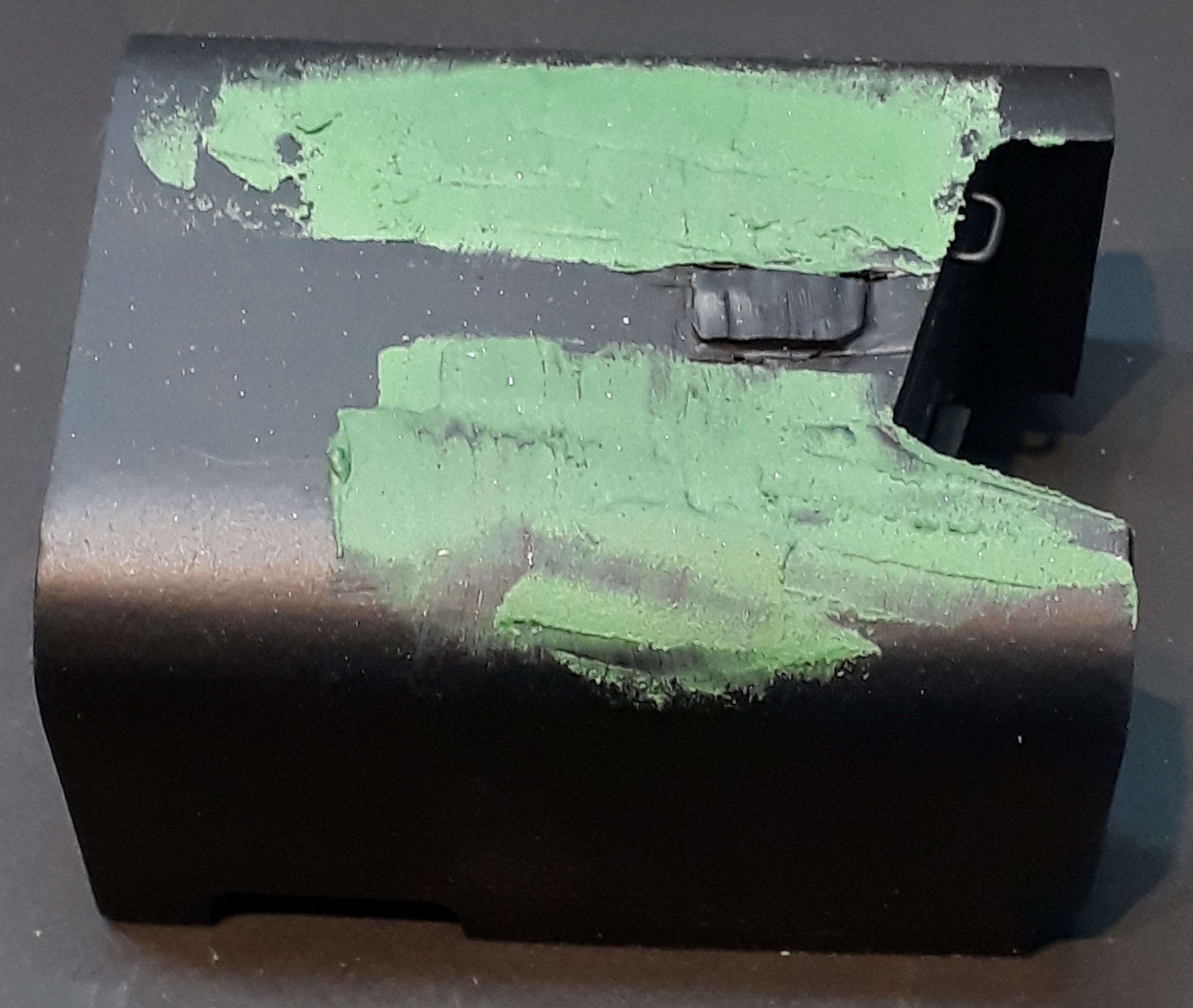 Next up is to add some filler. This is a cellulose putty that I sell and with a bit of cellulose thinners on a knife blade it can be smoothed out across the area in need of filling.
This is where your wet and dry on a flat stick comes in. Its used wet and is pressed against the filler and worked back and forth keeping it flat. It will take the filler off the high spots and leave it in any holes dug with the cutting wheels and sanding discs.
Here’s a snippet for you: The filler comes in various colours, green, grey & white, for a reason. The idea is you pick a contrasting colour to the base colour so you can see how you are doing.
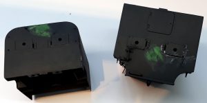
You should see the edges feather out to nothing. The filler tends to shrink as it sets so in areas where it was applied thicker like filling the holes in the ends a repeat application was needed.
The end are going to be the trickiest parts of what comes next and may decide whether that plan actually works. More on that later. The ends had something like 3mm diameter holes in it for the headlight wires. Way too big and way to obvious so they were filled in and will be re-drilled smaller and lower.
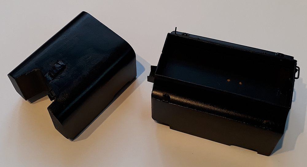
With the filling done to my satisfaction the tanks were given a coat of gloss black and set aside to fully harden. The black will either be the finished colour or just a border.
BODY MANGLING
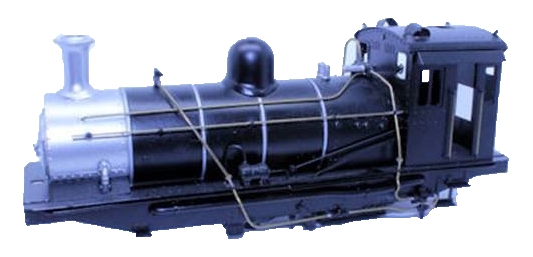
The body offends my eyes!
It took a long time for me to realise what it was about it that was getting to me but eventually I decided on these things: –
- The underframe was too open, showing too much daylight.
- What on the real thing are copper pipes don’t look right in undersized brass and with too angular bends.
- The lack of glazing in the cab is just wrong.
- Its too shiny.
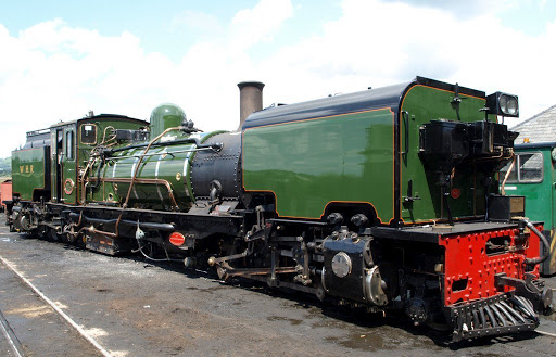 Hopefully this view of 143 stood outside Boston Lodge shed illustrates the daylight issue. Basically, you can’t see under the engine due to both bits of engine and the shadows it all casts. The two biggest items are the much larger ash pan that the engines now sport as they are designed to keep all their ash in for a trip to mitigate the fire risk. Also there are a couple of cylinders nearer the front that are vacuum reservoirs.
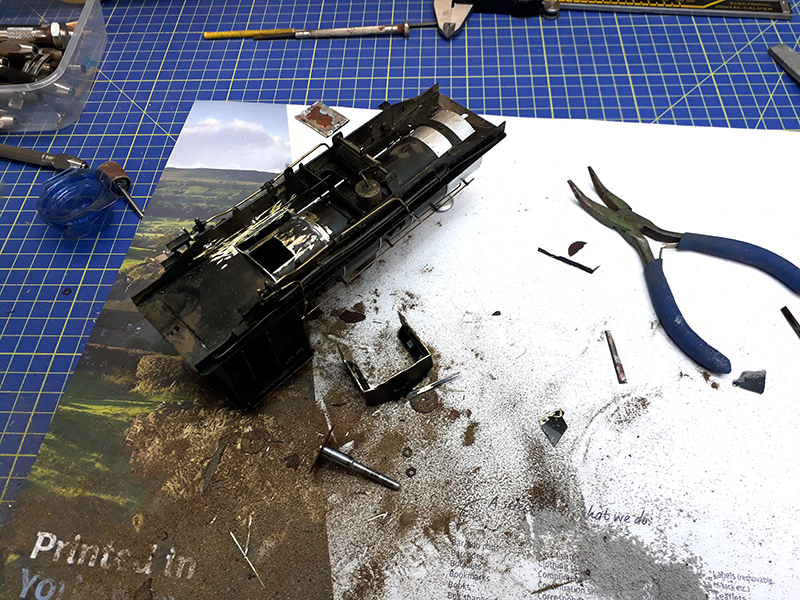 The old ash pan had to go! This was a real heart in your mouth moment. The destruction so far was reversible but this was really going to make a mess!
Once the first cut was done it was actually quite cathartic even though it did consume most of my stock of cutting discs and a good few sanding drums.
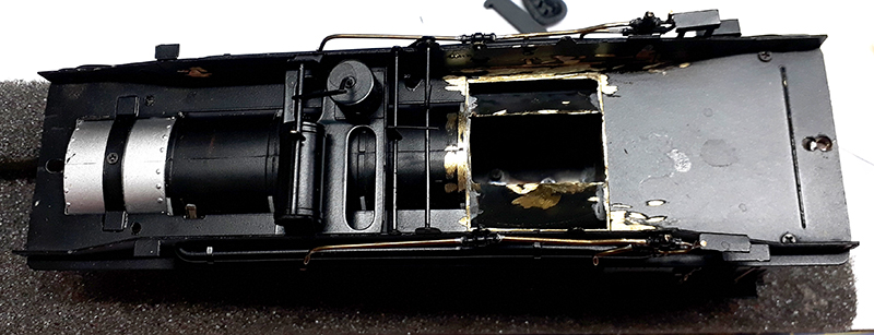
The result is that the firebox bottom and the ashpan have gone and there is now a big hole giving access to the inside of the boiler.
That has certainly revealed daylight under the engine!

Then I got a bit carried away.
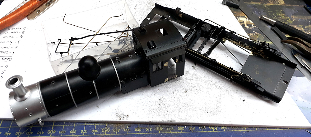 Its in lots of pieces now with lots of details removed. Its going to allow me to do the boiler painting more easily but its also going to require some CAD works done as some of the details also need to be replaced.
Luckily, I have a lot of NGG16 drawings as scans.
BIG DECISION
Dare I tell the customer what I have done to his loco?
BOGIES
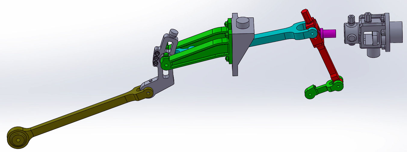 I suppose I’d better mention the trucks as some readers will know that I designed and produced a load of valve gear parts for an NGG16 so you might expect me to use a set on this model.
I am afraid that isn’t going to happen on this one. Basically, its because the basis of this loco is one of the ready to run ones so the trucks are all assembled and working. Taking them to bits would be a step too far this time. It would only really be practical to use them on a set of bogies being built from scratch.
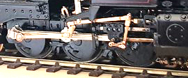 They do make a big difference as can be seen on this model built by Nick Dunhill.
WHAT NOW
 I suppose I had better start trying to put it back together.
On the trucks, so far, they have had Kadee couplers fitted. As you have seen above the tanks are finished in gloss black. The sand boxes have been removed and will be modified a bit before going back.
Missing from the loco was the auxiliary oil reservoir that goes between between the sand boxes on the ends and provides the mount for the headlight. Despite the loco currently having automotive headlights this picture shows it with a Stones Headlight which is what the model with have.
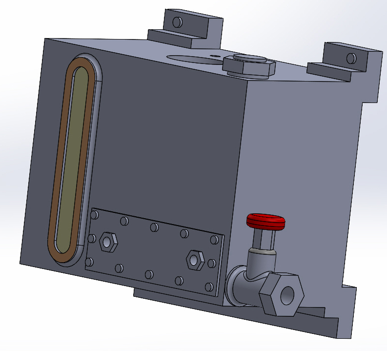 I fired up SolidWorks and produced this 3D CAD drawing and 3D printer print file.
The sizes for this were estimated from pictures to look right between the sand boxes.
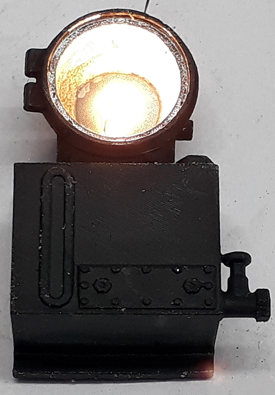
I have used the Stones headlight from my Darjeeling loco kit and fitted it with a micro LED. Still to add is the glass for the lamp as it will probably have a blank fitted first whilst the model is painted and weathered.
A water filler of the current style has also been drawn and printed.
This shows the print of the oil reservoir in unfinished resin and with the headlight lit from a test supply. On the loco it will be powered from the DCC decoder.
The other big thing needing to be changed is the ashpan especially now that I have rendered to old one as scrap brass and broken carborundum discs.
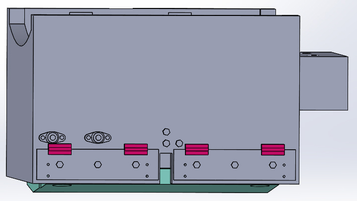 The current ashpan design on the real loco has had a lot of design put into it to ensure it has the capacity for a full trip and, working with the spark arrestor, prevents active sparks or embers escaping. For the model I have done the CAD to represent the proportions and look of it whilst fitting it around the DCC decoder adaptor board.
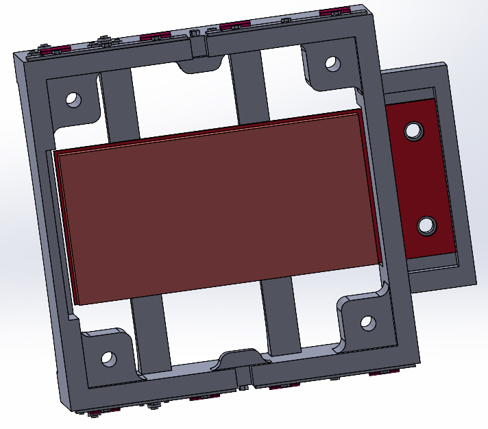 I could probably have stuffed the decoder through the hole in to the boiler but I am using this exercise to try some ideas for other kits in development so wanted to use a DCC adaptor board to wire all the loco’s wires to it before the decoder is installed.
The adaptor is designed to take a PLUX 22 decoder.
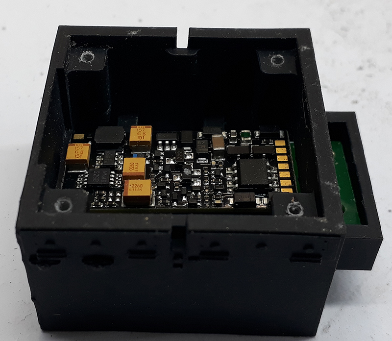 I am pleased to say the prints came out as I had hoped. Seen here with the adaptor board just resting in place.
This is probably as far as this episode is going to go on modifying the loco. Assembly of the ashpan, adaptor and other bits has been thwarted by my own stupidity. I printed the holes and then tapped them out for m1.6 screws to then discover my box of all manner of titchy metric screws hasn’t any M1.6 screws in it. Some are on the way but I’ll pause construction there for this evening. That said the 3D printer is still at work making some new vacuum cylinders and reservoirs.
WHAT COLOUR IS IT GOING TO BE MR?
Lined red or unlined black. Whichever happens it will be weathered as a working engine. I had better explain the indecision. I want to do it lined red which brings me on to the `big experiment’ and why I have been saying “more later” through this blurb.
 My cunning plan is to try and emulate the `vinyl wrap’ they do on the big railway with decals.
Having an un-built kit I was able to scan the etches and and scale them in CAD so as to draw the lining and colour panels to the right size. My drafting skills are always going to be better than my lining skills so, if this works it should give a neatly lined model. Tom at Endon Valley Custom Decals has produced the sheets for me.
The sides of the tanks and the cab should be relatively easy to do providing I can get all the bubbles out. Getting the fronts of the tank and bunker done could be tricky whilst I am really not looking forward to doing the cab front.
So here’s how it shapes up. I try adding the red decals to the tanks. If that works out then it’ll be a red engine. If that turns out to be a nightmare then it’ll be a black engine.
If we go with red then the tricky thing becomes matching a painted red for the boiler barrel. Painting that was the other thing I was dreading but the final rash of dismantling all the fittings off the boiler just made that a lot easier.
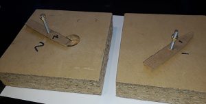
One thing that will be important is that extra pair of hands to hold the bunker and tank whilst I need both of mine to work with the decals.
To that end I have made these two fixtures to hold them down whilst I work on them. I suspect it will be a slow job as each face will need its decal applied, treated with decal softener, teased into place, treated with decal setting solution before being left for a couple of days to harden before its safe to work on another face..
Doing the first face might have to be the next task as the livery question needs an answer before I start reassembling the body.
I might get one face of each of the tank and bunker done tomorrow morning but all action is postponed in the afternoon due to live T20 cricket being on the gogglebox.

Wow, you are in a league or your own! I’ve bashed a lot of locomotives but never aspired to that!
I also own a San Cheng NGG16; on the outer box is the hand written notation “1 of 5 Red NGG16 Garratts” but there is no label (I bought it from a friend who was the original owner). Do you have any idea how many San Cheng built in total?
Scott, as I said with hindsight I wouldn’t have started from here. I don’t know how many San Cheng did but I can be pretty sure that non black ones are as rare as rocking horse dung.
With regard to THE BIG DECISION above.
Yes the owner does know (its me!)
Looking forward to next episode!
I always fancied building one of these kits. You have made me happy that I never aquired one now!